Southern Machinery provides professional SMT peripheral equipment


HIGH SPEED DISPENSING OF SURFACE MOUNT ADHESIVE BETWEEN SOLDER PASTED PADS
HIGH SPEED DISPENSING OF SURFACE MOUNT ADHESIVE BETWEEN SOLDER PASTED PADS
Introduction
Surface mount
adhesive has been a part of electronics manufacturing applications from
the beginning of SMT. It has been used, in conjunction with wave
soldering processes, to successfully solder millions of components to
the bottom sides of printed circuit boards. In an effort to make the
manufacturing processes more robust and to improve the quality of the
assemblies, a solder paste printing step and a reflow soldering step
have been added to many traditional bottom side assembly lines. These
operations are added in order to decrease defects such as missing
components and insufficient solder joints. Both SMT (double sided
reflow) and Through hole (mixed SMT/THT) processes can benefit from this
process utilizing adhesive and solder paste. Some of the process
considerations are nozzle design, pad design, PCB layout, stencil
design, and adhesive properties. This article will deal with the
characteristics that must be considered in setting up this process, how
it can be implemented successfully, and typical line configurations
associated with this process. The major foundation of traditional
bottom side assembly processes is the adhesive.
Adhesive Selection
When selecting an
adhesive for applications involving the dispensing of surface mount
adhesives between solder pasted pads, it is important to choose an
adhesive that is formulated to give very specific rheological, or flow
properties. The adhesive selected should be formulated to allow for a
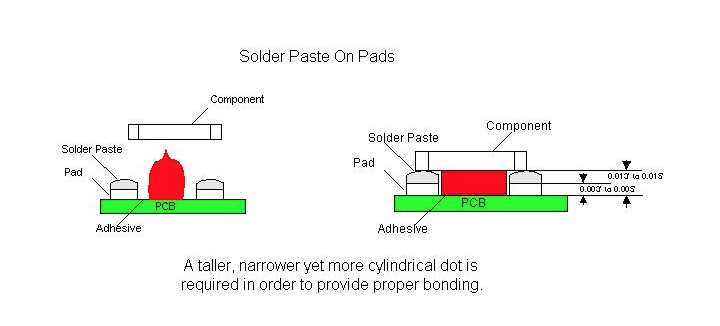
higher profile dot that exhibits very little slump. This will allow the
glue to contact the component, above the height of the solder paste
deposition, when the component is placed. Dots dispensed for this type
of application should have a tall, cylindrical shape as opposed to the
typical triangular Hershey kiss dot profile. The typical profile may
not allow the glue to properly adhere to the component prior to curing
and then hold the component through wave soldering. This will cause a
large number of missing component errors to be seen following the wave
soldering operation. Excessive missing components following manual
assembly may also be seen because the glue joint is not large enough to
provide the strength needed to hold the components in place.
The surface mount
adhesive chosen for these applications must also have a high green
strength in order to hold the component prior to the curing process. It
is this green strength that also helps the adhesive to maintain the
tall cylindrical dot shape needed when dispensing between solder pasted
pads. Without it the adhesive deposit will slump, losing contact area
with the component, and causing a decrease in the strength of the
adhesive joints.
In adhesive
dispensing processes utilizing heat, it is difficult to achieve the
necessary dot height. By applying heat to the adhesive, the material’s
viscosity is lowered, allowing it to flow more easily. This type of
flow characteristic will cause the adhesive dot to slump after
dispensing. Problems related to the adhesive not contacting the
component (missing components after wave soldering, etc.) will increase
in frequency, as well as the number of opportunities for defects such as
pad contamination to occur.
Board Design
Typically,
surface mount component pads are designed for either adhesive deposition
or the screening of solderpaste. The pad spacing is generally smaller
for solderpaste application as opposed to that of adhesive deposition.
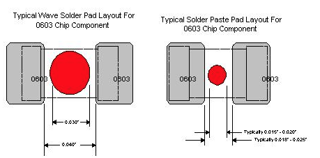
For example, the component pad spacing between the pads of a 0603 chip
cap/resistor is typically 0.020”, if the board was designed to be screen
printed with solderpaste. The pad spacing for the same board can be
0.040” if adhesive deposition was to be utilized. A 0.030” diameter dot
of adhesive would easily be recommended for use if the component pads
on the board were indeed designed for adhesive deposition. However, if
the pad design for the same board was originally designed for
utilization of solderpaste, as a method of adhering the component to the
board, obviously, an 0.030” diameter dot of adhesive would be too
large, as the spacing between the pads is now 0.020”. A 0.015” to 0.018”
diameter dot is required for this particular application.
In designing pad
spacing and component spacing, the height of the pad and the solder
paste deposition must also be taken into consideration. Typically, the
height of an adhesive dot is one half the diameter of the dot.
Depending upon the material used for the pads, it would be possible
design a board which would be impossible to print and dispense adhesive
on. If the typical dot size for a 0603 component were 0.015” to 0.018”,
the height would be approximately 0.0075” to 0.009”. If the thickness
of the stencil utilized to print the solder paste was 0.006” to 0.007”
this might not allow the glue dot to contact the component body on some
types of board finishes. For example, a typical HASL finish is
approximately 0.003” thick. If the thickness of the stencil utilized
were 0.007”, the adhesive dot would have to be at least 0.011” to 0.012”
tall to properly contact the component. This would require
approximately a 0.022” diameter dot. This is why the rheology of the
adhesive is so important. If the adhesive slumps at all after
dispensing, it may not properly contact the component. The nozzle
design also plays a part in the development of the correct dot for each
application.
Nozzle Design
When selecting a nozzle for use in dispensing adhesives the main characteristics that must be considered are nozzle
design, standoff size and placement, and nozzle ID. A relationship
exists between these characteristics and the adhesive dot diameter.
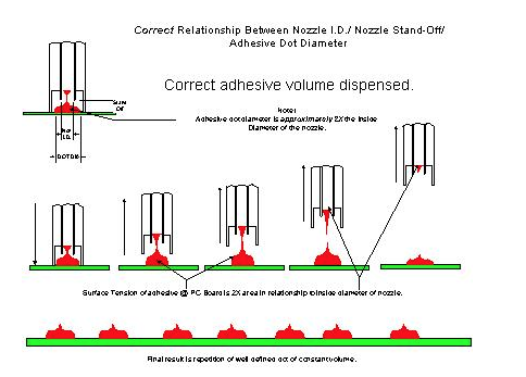
When the adhesive volume is dispensed, the surface tension of the
adhesive on the board, should be twice that of the surface area of the
adhesive at the nozzle tip. If this condition exists, as the nozzle
retracts, the adhesive will snap off clean from the nozzle and leave a
well-defined dot of constant volume on the board. The nozzle must be
chosen based upon the size dot that is required by the application.
Nozzle selection
refers in this case to specific nozzle specifications for a known dot
size requirement. The dot size requirements can be derived from the
board design being utilized or specifically the pad spacing of
components. Reference pad spacing previously discussed in this paper. It
is not uncommon for Manufacturing Engineer personnel or Quality
Engineering personnel of a printed circuit board manufacturing facility,
to inquire what a recommended adhesive dot diameter should be for a
particular component type. Much has been written in regards to
recommended surface mount component pad designs and layouts for bottom
side applications. Topside pad designs are also used on bottom side PCB
fabrication. However these guidelines are rarely utilized. The pad
spacing for a particular component for each individual customer product
is unique.
Because the pad
spacing for most typical surface mount components is not standardized
from one customer product to another, it becomes a challenging task when
recommending what tooling should be utilized to satisfy a particular
customers’ adhesive deposition requirement for a particular component.
Note that the
volume of adhesive needed to maintain the component in place during the
high speed placement or wave solder process may be larger than possible
for some specific pad designs.
The nozzle standoff
can be defined as the distance from the tip of the dispensing surface
to the end of the mechanical standoff. The nozzle standoff is used to
maintain the distance between the PCB and the dispensing tip. Most
dispensers in use today are designed to utilize some sort of mechanical
standoff with the nozzles. The standoff usually dictates, to some
degree, the height of the dispensed dot
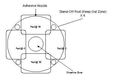
Typical designs for
nozzle standoffs are the castle design, the post design, or a dual post
design. For applications utilizing surface mount adhesive between pads
that have had solder paste applied to them, a single post design nozzle
is the most appropriate. In this type of application the standoff
should be set at 45 ° , 135 ° , 215 ° , or 315 ° around the pad circuitry.
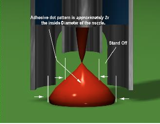
When selecting the
correct nozzle ID a rule of thumb is that the nozzle ID should be one
half of the required dot diameter. This will allow for the correct dot
diameter to be dispensed so that the glue snaps away from the nozzle
without contamination. By beginning with this guideline, the
approximate nozzle diameter can be determined, and then adjusted based
upon the material utilized.
Stencil Printing Considerations
When printing
solder paste prior to dispensing surface mount adhesive, there are some
stencil design considerations that must be taken into account. The
thickness of the stencil is important because it will determine the
height of the solder paste depositions. This also determines the
minimum height of the dot that must be dispensed in order to properly
contact and hold the component. In applications where wave soldering
will follow manual assembly, a smaller stencil thickness may be used
because the ultimate solder joint quality will be determined by the wave
soldering operation. It may also be beneficial, on pads with very
tight pads spacing, to undercut the stencil so that as much space as
possible is available for adhesive deposition.
Adhesive Curing
When printing
solder paste and dispensing epoxy between solder pasted pads a
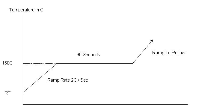
specialized cure cycle is required. Curing epoxy at 150º C is a
bondline temperature that should be verified with thermocouples at
various locations. Curing epoxy at temperatures above 160º C can cause
the adhesive to become brittle, leading to possible component loss
during the solder wave process. The solution for this is that the epoxy
must be cured at 150º C for about 90 seconds prior to ramping to the
reflow temp. This type of reflow takes into account the adhesive cure
as well as the solder paste reflow. Care should be taken to check the
quality of the solder joints achieved with this profile. The graph
below is a sample of what the cure cycle should look like. The final
profile should take into account the recommended profiles from both the
adhesive and from the solder paste manufacturers.
Placement Machine Considerations
When selecting a
placement machine for use in a process utilizing the dispensing of
surface mount adhesives between solder pasted pads, it is important to
consider the accuracy and the repeatability of the placement machine
down line. In typical top side applications utilizing solder paste
printing, when the solder paste is reflowed, the forces associated with
the solder, automatically center the component, within reason, on its
pads. When glue is added to the process this does not occur because the
glue resists these forces since it is cured prior to the reflowing of
the solder paste. It is important to consider all of the machines in
the line when developing this type of process.
Typical Manufacturing Line Configurations
Traditional Bottom Side Line

GDM Adhesive Dispenser
Vitronics Reflow Oven
HSP Chipshooter
Typically, a
traditional bottom side manufacturing line includes an adhesive
dispenser, a chipshooter to place the bottom side components, and an
oven to cure the adhesive. This line will be followed by a wave solder
machine, which will in turn be followed by an inspection and/or rework
station.
The first thing
that must be considered when setting up any manufacturing line is the
type of components and assemblies that are going to be used or built on
it. A traditional bottom side line can be used simply to apply glue to a
printed circuit board, place components on the board, and then cure the
glue in order to hold the parts onto the board prior and during wave
soldering and manual assembly. In this type of application the green
strength of the material determines whether components stay in place
during placement operation on the chipshooter. The post cure strength
of the adhesive determines whether or not the components will stay on
the board during manual assembly and handling. This makes the choice of
glue very important. After wave solder, using this type of line, parts
may be missing due to missing or unacceptable adhesive dots or some may
have be knocked off the board during manual assembly or handling. Care
should be taken to control the forces that these assemblies are
subjected to. This line is very basic in its functionality but can
reliably build products when implemented correctly.
Bottom Side Line With Solder Paste Application

HSP Chipshooter
DEK Stencil Printer
Vitronics Reflow Oven
GDM Adhesive Dispenser
A bottom side line,
that includes solder paste application, incorporates a system for
applying the solder paste (stencil printer or high speed dispenser), an
adhesive dispenser, a chipshooter for the bottom side components, and an
oven to cure the adhesive and reflow the solder paste. A wave solder
machine and an inspection and/or rework station will then follow this
line.
This type of
manufacturing line is more flexible than the previously discussed line.
For bottom side applications, this configuration provides greater torque
strength due to the adhesive being combined with solder paste. This
will assist in reducing the number of missing part defects present in
the assembly. This type of line also helps to reduce problems related
to the wave soldering operation (insufficient solder). In this type of
application, the dot height is important to consider because the dot
must be tall enough to contact the component even above the solder paste
deposit. Consideration also must be given to the design of the stencil
used to print the solder paste and the design of the nozzle used for
high speed dispensing operations. Both of these points can turn into
problems later if not considered properly.
Mixed Technology Top/Bottom Assembly with Solder Paste Application

Vitronics Reflow Oven
HSP Chipshooter
GDM Adhesive Dispenser
DEK Stencil Printer
GSM Flexible Placement
A mixed technology
line for assembling top and bottom side products includes a system for
applying the solder paste (stencil printer or high speed dispenser), an
adhesive dispenser, a chipshooter to place the bottom side components, a
flexible placement machine to place top and bottom side components, and
an oven to cure the adhesive and reflow the solder paste. A wave
solder machine and an inspection station will then follow this line.
The inspection station however, should see limited use because of the
robustness of this process.
This manufacturing
line is more flexible than either of the previously discussed lines.
Like the bottom side manufacturing line with solder paste, on bottom
side applications, this configuration provides greater torque strength
due to the adhesive being combined with solder paste. This assists in
reducing the number of missing parts present in the assembly. This
also helps to reduce problems related to the wave soldering operation
(insufficient solder). In this type of application, the dot height is
important to consider because the dot must be tall enough to contact the
component over and above the solder paste deposit. Consideration also
must be given to the design of the stencil used to print the solder
paste and the design of the nozzle used for high speed dispensing
operations. This line also can be used for topside applications
including the deposition of solder paste, chip placement and flexible
placement (QFPs and BGAs for example). This type of flexible
manufacturing line has become the choice for contract electronics
manufacturers because it offers a simple, total assembly solution.
Conclusion
The dispensing of
surface mount adhesives has been a part of electronics manufacturing
since the development of surface mount components. In an effort to make
the processes involved more robust, solder paste has been added to many
manufacturing line configurations. This configuration helps to
eliminate defects such as missing components and insufficient solder
joints following wave soldering.
In order to
implement this process there are a lot of considerations that must be
taken into account. The type of adhesive used must have rheological
properties that allow for a tall, cylindrical dot versus the typical
Hershey kiss shaped dot. This type of dot is required to properly
adhere to the component when it is placed on top of the solder paste
deposits. In order to obtain the correct dot height, the board design
must be considered carefully. By designing in the correct pad spacing,
implementation of this process is much simpler. The volume of solder
paste required must then be determined as well as the design of the
stencil. The required adhesive dot size must be considered when
designing the stencil. After the board is designed and the volume of
solder paste required has been determined, a nozzle must be designed to
provide the correct dot diameter with standoffs that will not become
contaminated with solder paste. After the adhesive is deposited and the
chips have been placed, the glue must be cured and the solder paste
must be reflowed. The profile used for this process must be developed
from the adhesive and the solder paste manufacturers’ recommended
profiles. Finally, the type of assemblies that are going to be built
must be considered when developing a manufacturing line that will meet
your needs now and in the future.
By carefully
considering all aspects of your manufacturing process, the dispensing of
surface mount adhesives between solder pasted pads can help eliminate
defects associated with typical electronics manufacturing processes.
This process helps to eliminate problems such as insufficient solder
joints. In applications where only glue was previously utilized, this
type of process can help eliminate defects such as missing components,
that can occur as a result of handling and manual assembly. By taking
time to consider the characteristics of your manufacturing process, the
correct line configuration and process parameters can be developed to
build the highest quality assemblies possible.
How to evaluate SMT Auto Insertion machine supplier
Quality System Assessment Summary Report
|
Supplier: |
Commodity Team: |
Primary Audit Contact: |
|
Address: |
|
|
|
|
Supplier Commodity/Product Specialty: |
Audit Team: |
|
Phone: |
||
|
Fax: |
|
Elements |
Max. |
Audit Date:
|
Re-audit Date: / / |
% Improvement |
Physical/ Logistical Capabilities (for information only) |
Score (0-3) |
|
|
Score |
Score |
Score |
A. Geographic location |
3 |
|
1 Management Responsibility |
|
|
B. Plant condition / size |
3 |
|||
|
2 Quality System |
|
|
C. Employment / labor recruiting |
2 |
|||
|
3 Contract Review |
|
|
D. Finance resources |
3 |
|||
|
4 Design Control |
|
|
E. Pricing history |
2 |
|||
|
5 Document and Data Control |
|
|
F. Equip. Condition /age / application
|
2 |
|||
|
6 Purchasing and verification
|
|
|
G. Backlog / capacity status |
2 |
|
7 Customer Supplied Products |
|
|
Yes/ No for following |
|
8 Product Identification and Traceability |
4 |
|
H. ISO / QS 9000 certified |
Yes |
|||
|
9 Process Control |
|
|
I. Design Capability |
Yes |
|||
|
10 Inspection and Testing |
|
|
J. Quick turn/prototype capability |
Yes |
|||
|
11 Control of Inspection and Test Equip.
|
12 |
|
K. JIT capability / Kanban |
Yes |
|
12 Inspection and Test Status |
2 |
|
||||
|
13 Control of Nonconforming Product |
|
|
||||
|
14 Corrective and Preventive Action |
6 |
|
Calculations: |
|||
|
15 Handling, Storage, Pack. and Delivery |
9 |
|
1. Quality System Score (%): |
|||
|
16 Control of Quality Records |
5 |
|
Total Audit Score x 100 |
|||
|
17 Internal Auditing |
10 |
|
(Total Max. Score – N/A Score) |
|||
|
18 Training |
6 |
|
2. % Improvement: |
|||
|
19 Servicing |
4 |
|
(New Score – Previous Score) x 100 |
|||
|
20 Statistical Techniques |
30 |
|
Previous Score |
|||
|
21 Continuous Improvements |
|
|
|
Total Score |
|
|
Auditor’s Signature:
|
|||
|
% Score |
|
Date: |
Quality Control for Auto Insertion machine manufacturing
Quality Control
Every Auto Insertionl machine
is subjected to a Quality Acceptance Test (QAT) before being shipped to
its customer. There are 4 phases to a QAT:
Phase I – Pre-Dry Cycle
The
appropriate pattern program is loaded and the machine performs a short
part run with all motions and mechanisms functioning to check setups and
speed. All data is recorded on the machine’s event log.
Phase II – Dry Cycle
Can
only occur after successful completion of the Pre-Dry Cycle. The
machine is run with all motions and mechanisms functioning but without
boards or inserting components for a pre-specified period of time. All
data is recorded on the machine’s event log.
Phase III – Integrity Run (Final Run)
Can
only occur after successful completion of the Dry Cycle. This is a
simulated production run to check insertion performance and speed.
Results are recorded on the machine’s event log.
|
|
Axial Inserter S4000 |
|
|
Radial Inserter S3000 |
|
|
Phase I |
|||||
|
Parts Run |
|
2000 |
|
2000 |
|
|
Insertion PPM * |
|
0 |
|
0 |
|
|
Intrinsic Availability ** |
|
100% |
|
100% |
|
|
Phase II |
|||||
|
Length of Run |
|
12 hrs. |
|
12 hrs. |
|
|
Intrinsic Availability |
|
95% |
|
95% |
|
|
Phase III |
|||||
|
Minimum Parts Run |
|
20000 |
|
20000 |
|
|
Allowable Insert Errors |
|
10 |
|
20 |
|
|
Intrinsic Availability |
|
95% |
|
95% |
|
|
Acceptable PPM Levels |
|
500 – 1000 |
|
1000 |
|
|
Confidence Level |
|
95% |
|
95% |
* (# of good insertions / total # of insertions)
** (# of hours the machine is ready to run / total # of hours machine planned to run)
Phase IV – Customer Acceptance (Optional)
Can
only occur after successful completion of the Integrity Run. The
customer visits the factory to watch verify the machine’s ability to
meet performance requirements. The customer’s production run is
simulated and all options are verified and explained.
For any further questions regarding the customer acceptance procedure, please contact:
Albert Wen
Albert@smthelp.net
Phase V – Preproduction Acceptance (At customer site)
Service engineer installs the machine and assures it is setup
and running with the same degree of operational efficiency as at the
factory.
Southern Machinery WARRANTY POLICY ON ALL NEW Machines
WARRANTY POLICY ON ALL NEW Machines
Southern Machinery warrants its products to be free from defects in materials and workmanship for a period of one year from completion of installation, provided the products are installed as specified by Southern Machinery, maintained by qualified service personnel and the products are operated in accordance with published operating procedures. For purposes of the foregoing warranties the “completion of installation” shall be that date, within 90 days of shipment of Southern Machinery’s products from its factory, on which the products are installed and operating to the published specifications. If the customer believes a product to be defective in material or workmanship, or failing to meet the specifications, the customer shall notify Southern Machinery of such alleged defect or failure. Southern Machinery shall have a reasonable opportunity to investigate any alleged defect or failure, and upon confirmation of its existence Southern Machinery shall promptly remedy the same by repair or replacement, at its discretion and without charge. The seller warrants parts repaired or replaced for the duration of the original warranty period.
The warranty does not apply to:
1. Consumable parts as they are defined in this document.
or
2. Defects or failures as a result of non-compliance with U Southern Machinery’s installation specifications.
or
3. The customer’s failure to perform the recommended normal maintenance, set up and the adjustment of the equipment.
or
4. The customer’s alteration / modification to the equipment without Southern Machinery’s prior written approval.
or
5. Damages to the equipment resulting from non-compliance with published operating procedures.
or
6. The use of replacement parts not supplied by Southern Machinery or Southern Machinery’s approved suppliers.
Definition of Consumable Parts (Non Warranty):
A) Machine parts that come in direct contact with component processing.
Examples are, but are not limited to, insertion head tooling, chain clips, lead cutter tooling, etc.
B) Maintenance/bulk items.
Examples are, but are not limited to, lubricants, adhesives, light bulbs, fuses, seals, o-rings, etc.
All other machine parts are warranted for 12 months from the machine in-service date, completion of installation.
Disclaimer Statement:
The life expectancy of consumable tooling is dependent on proper preventive maintenance, proper machine set-up, and the type of component used by the customer. A customer may experience greater life expectancy or less life expectancy depending on the above.
SMT machines Cpk Conversion to Defects over Time at Typical Run Rates
When defect rates are higher than what the machine’s Cpk would indicate
according to this table, it is due to one of several things: machine set-up or
maintenance issues, process issues, component imperfections, etc.

Auto Insertion machine Competitive Analysis – TDK AC7 vs Universal VCD
Axial Products Competitive Analysis
|
Competitor |
Location |
Key Weaknesses |
Key Strengths |
Comments |
|
TDK (Rank 2) |
Japan/U.S. |
No Axial experience No previous Axial machines in product mix, offering only a SH VCD (no Sequencer, DH, etc.) Axial product offering is VERY similar to Dynapert V12000. Possible patent infringements on Dynapert design. Support infrastructure is inferior to UIC’s. |
Low price machines Field proven reliability of Radial Inserter Large multi-national installed base for Radial Inserter Japanese firm, thus strong JMA loyalty Asian company, thus understands Asian business needs Operates in Microsoft Windows interface, which provides immediate productivity feedback Financially sound and stable |
Offer a SH VCD – Avisert AC-7 |
TDK Competitive Summary
|
|
AC-7 Avisert Features: · Board offset correction · Insertion hole correction · Ammo or reel input packaging · Push button control panel · Microsoft Windows interface · Intelligent operator message feedback · Servo driven cam operated insertion head · Servo motor driven rotary table · Available Options: – Pass through capability – Throughput optimizer – Flexible work board holder – Touch screen – Pattern repeat – Multi tier security software – Optical safety device – Integrated machine enclosure |
Key Sell Against Points:
Universal offers a complete Axial product line; Single Head, Dual Head, VCD Sequencer and Sequencers while TDK offers a single Axial machine.
Universal completes the IM product offering with Radials and Special Products which include Eyelet and Pin Inserting Machines, and 3-Span Radials.
We offer optional Universal board handling on most models.
Universal offers a superior training, service and support infrastructure.
We offer industry leading cost per insertion and the highest throughput per square foot of floor space.
UIC Strengths and Proof Points:
|
UIC Strengths |
Benefit |
For the Customer: |
|
Machine designs allow flexibility in the production environment. |
Universal offers a complete IM product line of Axial inserters, Sequencers and combination machines, as well as Radial product offerings. Universal board handling is optional for machine integration. |
Discuss customer need for factory integration. Possible future need for increased automation. |
|
High value for the price, and fastest inserters in the industry. |
Dual Head machines provide the highest throughput in the industry, 32,000 cph, a cost effective approach for high volume applications. |
Ask the customer to compare cost per insertion. |
|
Superior service, support and training. |
Excellent investment protection. UIC is a respected and secure provider of insertion equipment. Pre and post sale assistance with specific applications and systems integration. |
Ask the customer to compare UIC’s support infrastructure (tech. specialists, spare parts, FE response time) to Panasonic. Also discuss unique value benefits – Uptime 100 and Tech Advisor. |
TDK Strengths and Counter Points:
|
Competitor Strength |
The Facts |
For the Customer: |
|
Perceived high throughput (16,000 CPH). |
The throughput Nepcon Tokyo 觀appeared closer to 10,000 CPH. Noisy. |
Demonstrate UIC’s commitment to reducing customer costs by: 1. Comparing cost per insertion. |
|
Single insertion head provides better stability and less maintenance and setup. |
Dual head machine is the highest throughput inserter in the industry with exceptional reliability and insertion performance. Single head machine offers competitive cost per insertion with all the other values of UIC. |
Demonstrate UIC commitment to customer support with: 1. Service and support, including PM schedules and maintenance manuals. 2. Uptime 100 program. 3. Tech Advisor. 4. Superior training program. |
|
Priced competitively in the 80K – 106K range. |
Targeting existing Dynapert accounts where support requirements are minimal. |
Demonstrate UIC’s commitment to reducing customer costs by: 1. Comparing cost per insertion. |
|
Financial backing from a major IM provider. |
Very similar to Dynapert V12000 machine Possible patent infringements on Dynapert design. Not a complete product line, no complementary Sequencer available to date or board handling. May not have devoted TDK backing for service and support. |
Determine if customer is will to obtain investment protection: 1. From a supplier that may not remain in business due to legal problems. 2. Has revived very old designs. 3. Discuss Broome Engineering products for low cost entry and their ability to allow trade-up. |
Appendix – Reference Accounts and Testimonials:
|
Account Name |
Salesman to contact |
Comments |
|
AT&T Monterey, Mexico |
Michael Lewis |
TDK offered AT&T accepted an all expenses paid trip to Boston to evaluate the AC-7 but still prefers the UIC Dual Head machines. |
Axial Insertion machine Competitive Analysis – Amistar AI-6448 vs Universal 6241D
This paper compares Amistar’s Model AI-6448 Inserter/Sequencer and Universal’s Model 6241D VCD/Sequencer machines.
Amistar Corporation, head quartered in San Marcos, California, is a small company – 154 employees and ~ $20 mil in annual sales. Both resources and exposure are limited and Amistar predominantly sells via representatives. To my knowledge, manufacture of the Amistar Model AI-6448 was discontinued approximately 7 years ago. Because of this, current information about Amistar is limited.
Amistar advertises the AI-6448 on their web page as follows:
The Amistar AI-6448 is a fully automated Axial component inserter.
Stand alone automation: sequences & inserts in one operation
Cycle rate of 9,600 insertions per hour
Capacity: 64 cartridges, 88 reels
Automatic optical position correcting via PCS (Position Correcting Servo)
Axial component verifier
Lead protrusion inspection
Microprocessor control
Easy to program
Easy to use
Amistar’s approach to axial insertion with their model AI-6448 is very different from Universal’s. Axial lead components are cut at the dispensing head and dispensed down a tube via free fall (gravity) compressed air. The component is then recaptured at the transfer station for eventual insertion into the PCB. The Amistar machine has capacity for 88 reels and 64 cartridges, but no ammo pack capability. Each cartridge is kitted off line and capable of handling a maximum of 75 components. Some customers believe this feature works well for small production runs, although it does add another preparation step to the process, as well as additional component handling, which increases the potential for component damage and or errors.
Other differences from the method in which Universal handles axial components include the way in which components are centered. Amistar centers on lead end instead of the component body. This can lead to components being cut off-center and consequently effect insertion reliability.
In order to utilize the AI-6448’s method of transferring components to the insertion area, the positioning system is very low to the floor making it difficult to maintain and/or access. Universal FE’s have had the opportunity to evaluate AI-6448’s installed at customer locations and have reported concerns with the durability, accuracy and repeatability of the rotary table.
While the Amistar Model AI-6448 can be equipped with board handling, the method utilized is limited to stand-alone applications, not allowing for pass-through or in-line capability and takes up a lot of floor space.
In the past, Amistar has sold the AI-6448 when the prospective customer is interested in combined sequencing and insertion and price is a major factor. Typically, the price of the AI-6448 is much less than the 6241 in a similar configuration (similar in a sense that there are similar number of inputs). When speed, capability and machine performance are added to the equation, the AI-6448 is not as attractively priced. Because Amistar has not manufactured the AI-6448 in 7 years, no current pricing information is available to us.
|
Feature |
Amistar Model AI-6448 Axial Insertion Machine |
Universal Model 6241D VCD Sequencer/Inserter |
|
Speed |
9,600 cph |
16,000 cph |
|
Max PCB Size w/Board Handling |
20″ x 20″ (508mm x 508mm) |
19″ x 16″ (483mm x 406mm) |
|
Max PCB Size w/out Board Handling |
20″ x 20″ (508mm x 508mm) |
18″ x 22″ (457mm x 559mm) |
|
Max # of Inputs |
52mm only: 64 cartridges, 88 reels 26mm not available ammo pack not available |
52mm: 220 stations in 20 station increments 26mm: 220 stations in 20 station increments Reel and/or Ammo Pack |
|
Insertion Span |
Std:.300″ – .800″ 7.62mm – 20.3mm) 5mm: Not available |
Std: .300″ – .950″ (7.6mm – 24.1mm) 5mm: .197″ – .850″ (5mm – 21.6mm) |
|
Component Centering |
Component Leads |
Component Body |
|
Board Error Correction |
Yes |
Yes |
|
Verification |
Yes – limited capability |
Yes |
|
Lead Sensing |
Yes |
Yes – dual lead |
|
Rotary Table |
Yes |
Yes |
|
On-Line Programming |
Yes |
Yes |
|
Automatic Board Handling |
Yes |
Yes – designed and manufactured by Universal |
|
Part Transfer |
Chute |
Sequencer |
|
Refire |
Yes |
Yes |
|
Part Repair |
Automatic |
Semi-automatic |
|
Max Body Length |
.400″(10.2mm) |
.620″(15.7mm) |
|
Max Body Diameter |
.175″(4.5mm) |
.420″(10.69mm) – 2 x PCB thickness |
|
Lead Diameter |
||
|
Standard Tooling: copper lead |
.015″- .036″(.38mm – .9mm) |
.015″- .032″(.38mm – .81mm) |
|
Standard Tooling: copper lead |
.015″- .026″(.38mm – .66mm) |
.015″- .032″(.38mm – .81mm) |
|
5mm Tooling: copper lead |
Not available |
.015″- .032″(.38mm – .81mm) |
|
5mm Tooling: copper lead |
Not available |
.015″- .032″(.38mm – .81mm) |
|
Jumper Wire Capability |
Yes |
Yes |
|
Low Part Sensing |
No |
Yes |
Universal’s 6241D is still manufactured and design development activities continue to enhance and improve the machine as part of Universal’s ongoing commitment to the through-
hole market. In addition to the items listed above, recent enhancements in the Model 6241D product line include:
Axial Tech Advisor is available which provides Operators and Maintenance Technicians on-line, menu-driven diagnostic information and assistance on machine operation, troubleshooting, maintenance and repair at the time of need. It is available in English, Chinese and Spanish.
Newly designed jumper wire dispensing system provides fast, reliable and accurate wire feed and accommodates .45mm to .6mm wire diameters
Newly designed dispensing heads are easy to operate, greatly extend life of wearable parts and allow for quick changeover with minimal scrap.
The 6241D now offers a low-level Sequencer Add-On Module for easy reach loading. It features low part sensing to alert the operator before parts are depleted, allowing replenishment without interrupting machine operation, removable end scrap bins for easy clean out, and refire is offered on each dispensing head.
Precision WBH’s, both adjustable and fixed are available. Universal can also accommodate Amistar WBH’s.
The 6241D contains a 4 color light tower which signals machine operating status.
New and improved board handling increases system reliability, ease of PCB changeover and ease of assembly. (See SH BHS Improvements Presentation).
Newly designed 5mm tooling is now available for increased reliability, longer life and better handling of bent lead component input. (See 5mm Tooling Improvements Presentation). Customers have told us this tooling lasts three times longer than the old style tooling
Universal offers a AAA version of the VCD Sequencer machine that is capable of inserting 26mm input.
The 6241D is CE marked to meet all European health and safety standards.
While Universal does not offer conversion software for converting Amistar pattern programs, the Amistar programs could be treated as CAD data and translated via the CAD translator available in PPU. If your prospective customer would like to supply us with one of their programs and briefly explain the fields, we will review the program and offer suggestions for performing the translation.
And last, but not least, Universal offers a support infrastructure which includes a knowledgeable and experienced Field Service organization, world wide Training Centers and Parts Distribution Centers as well as an extensive installed base.