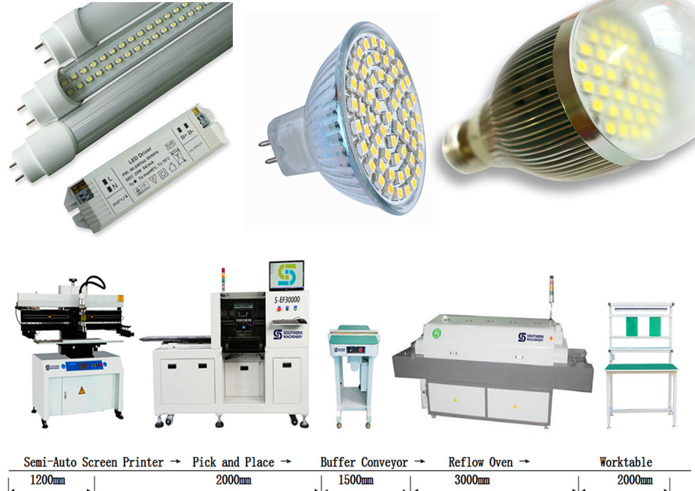
Southern Machinery provides professional SMT peripheral equipment

Quality Control for Auto Insertion machine manufacturing
Quality Control
Every Auto Insertionl machine
is subjected to a Quality Acceptance Test (QAT) before being shipped to
its customer. There are 4 phases to a QAT:
Phase I – Pre-Dry Cycle
The
appropriate pattern program is loaded and the machine performs a short
part run with all motions and mechanisms functioning to check setups and
speed. All data is recorded on the machine’s event log.
Phase II – Dry Cycle
Can
only occur after successful completion of the Pre-Dry Cycle. The
machine is run with all motions and mechanisms functioning but without
boards or inserting components for a pre-specified period of time. All
data is recorded on the machine’s event log.
Phase III – Integrity Run (Final Run)
Can
only occur after successful completion of the Dry Cycle. This is a
simulated production run to check insertion performance and speed.
Results are recorded on the machine’s event log.
|
|
Axial Inserter S4000 |
|
|
Radial Inserter S3000 |
|
|
Phase I |
|||||
|
Parts Run |
|
2000 |
|
2000 |
|
|
Insertion PPM * |
|
0 |
|
0 |
|
|
Intrinsic Availability ** |
|
100% |
|
100% |
|
|
Phase II |
|||||
|
Length of Run |
|
12 hrs. |
|
12 hrs. |
|
|
Intrinsic Availability |
|
95% |
|
95% |
|
|
Phase III |
|||||
|
Minimum Parts Run |
|
20000 |
|
20000 |
|
|
Allowable Insert Errors |
|
10 |
|
20 |
|
|
Intrinsic Availability |
|
95% |
|
95% |
|
|
Acceptable PPM Levels |
|
500 – 1000 |
|
1000 |
|
|
Confidence Level |
|
95% |
|
95% |
* (# of good insertions / total # of insertions)
** (# of hours the machine is ready to run / total # of hours machine planned to run)
Phase IV – Customer Acceptance (Optional)
Can
only occur after successful completion of the Integrity Run. The
customer visits the factory to watch verify the machine’s ability to
meet performance requirements. The customer’s production run is
simulated and all options are verified and explained.
For any further questions regarding the customer acceptance procedure, please contact:
Albert Wen
Albert@smthelp.net
Phase V – Preproduction Acceptance (At customer site)
Service engineer installs the machine and assures it is setup
and running with the same degree of operational efficiency as at the
factory.
Southern Machinery WARRANTY POLICY ON ALL NEW Machines
WARRANTY POLICY ON ALL NEW Machines
Southern Machinery warrants its products to be free from defects in materials and workmanship for a period of one year from completion of installation, provided the products are installed as specified by Southern Machinery, maintained by qualified service personnel and the products are operated in accordance with published operating procedures. For purposes of the foregoing warranties the “completion of installation” shall be that date, within 90 days of shipment of Southern Machinery’s products from its factory, on which the products are installed and operating to the published specifications. If the customer believes a product to be defective in material or workmanship, or failing to meet the specifications, the customer shall notify Southern Machinery of such alleged defect or failure. Southern Machinery shall have a reasonable opportunity to investigate any alleged defect or failure, and upon confirmation of its existence Southern Machinery shall promptly remedy the same by repair or replacement, at its discretion and without charge. The seller warrants parts repaired or replaced for the duration of the original warranty period.
The warranty does not apply to:
1. Consumable parts as they are defined in this document.
or
2. Defects or failures as a result of non-compliance with U Southern Machinery’s installation specifications.
or
3. The customer’s failure to perform the recommended normal maintenance, set up and the adjustment of the equipment.
or
4. The customer’s alteration / modification to the equipment without Southern Machinery’s prior written approval.
or
5. Damages to the equipment resulting from non-compliance with published operating procedures.
or
6. The use of replacement parts not supplied by Southern Machinery or Southern Machinery’s approved suppliers.
Definition of Consumable Parts (Non Warranty):
A) Machine parts that come in direct contact with component processing.
Examples are, but are not limited to, insertion head tooling, chain clips, lead cutter tooling, etc.
B) Maintenance/bulk items.
Examples are, but are not limited to, lubricants, adhesives, light bulbs, fuses, seals, o-rings, etc.
All other machine parts are warranted for 12 months from the machine in-service date, completion of installation.
Disclaimer Statement:
The life expectancy of consumable tooling is dependent on proper preventive maintenance, proper machine set-up, and the type of component used by the customer. A customer may experience greater life expectancy or less life expectancy depending on the above.
Auto Insertion machine Tooling Design vs. Range of Inserted Component Wire
1.0 INTRODUCTION
Do you have customers who are willing to simplify the Axial automated insertion process, speed up machines, lower preventative maintenance (pm) downtime and ppm levels and generally reduce manufacturing costs? If so, then this paper may interest you.
Universal Instruments Corporation is currently working to customize tooling for customers who have evolved their manufacturing processes to two and three step processes for Axial insertions, thereby dedicating machines to run a limited range of components. In step one for example, a machine inserts only 5mm insert spans and then in step 2, a second machine inserts various wire diameters. This is a radical change from the current manufacturing philosophy of fully populating a board in one pass through a machine. However, history has shown that by limiting the range of wire diameters inserted and then designing tooling to specifically handle that range, the manufacturing process becomes more controlled, insertion performance improves, pm downtime and ppm levels decrease and ultimately, manufacturing costs decrease.
Admittedly, this approach is not viable for every customer. Universal offers a variety of tooling configurations that if used according to specification, will provide excellent insertion performance. A customer may have no need to run a wide range of wire diameters or they may want to revisit their manufacturing process to make improvements. For those customers, Universal offers customized tooling for dedicated applications. Customized tooling will handle a limited range of wire diameters to optimize insertion performance and maximize tooling life.
This paper discusses the relationship between tooling design and wire diameter range of inserted components with the goal of creating an awareness and understanding of this relationship and it’s significance.
2.0 FACTORS AFFECTING THIS RELATIONSHIP
2.1 Depth of V-Groove of Outside Former
One important factor affecting the relationship of tooling design and range of insertable wire diameters is the depth of the V-groove of the Outside Former. Our current specifications for Axial tooling are as follows:
|
|
Standard |
High Density |
Large Lead |
5mm |
26mm AAA |
|
Bottom View of Outside Former |
|
|
|
|
|
|
Wire Diameter Range / Material |
Steel: .015”-.032” (.39) – (.82) Copper: .015”-.032” (.39) – (.82) |
Steel: .015”-.025” (.39) – (.64) Copper: .015”-.032” (.39) – .82) |
Steel: .025”-.032” (.64) – (.82) Copper: .025”-.042” (.64) – (1.01) |
Steel: .015”-.025” (.39) – (.64) Copper: .015”-.028” (.39) – (.72) |
Steel: .015”-.020” (.39) – (.51) Copper: .015”-.024”(.39) – (.61) |
|
Driver Tip Width |
.030” (.77) |
.030” (.77) |
.050” (1.27) |
.017”* (.44) |
.012”* (.31) |
Metric equivalents are bracketed
* Not entire width but dimension from edge of Driver Tip to side of Outside Former
When the wire diameter is smaller than the depth of the V-groove of the Outside Former, the lead has excess space and moves within the V-groove. This uncontrolled condition leads to a ‘weak’form.
|
|
|
V-groove with Small Lead Diameter
When the wire diameter is larger than the depth of the V-groove of the Outside Former, the yieldable Inside Former flexes to make room for the bigger lead. Continual flexing causes the O-rings to wear out which leads to a ‘sloppy’Inside Former and ‘weak’forms. Outside Formers have been known to split at the V-groove from continual stress. Long term, continual flexing will damage the Tooling Housing by loosening it and making it ‘sloppy’.
|
|
|
V-groove with Large Lead Diameter
The optimal condition is wire diameter equal to the depth of the V-groove of the Outside Former. In this condition, the lead is large enough so that is does not ‘move’within the V-groove, and yet it does not continually flex the Inside Former.
|
|
|
V-groove with Optimal Lead Diameter
When Standard tooling is compared to 5mm tooling, it becomes clear why 5mm tooling is less reliable when inserting components with large lead diameters than Standard tooling.
|
TOOLING |
DEPTH OF V-GROOVE |
WIRE DIAMETER RANGE |
|
Standard |
.028”(0.71mm) |
.015”-.032”(0.39mm – 0.82mm). |
|
5mm |
.018”(0.46mm) |
.015”- .028”(0.39mm – 0.72mm) |
The depth of the V-grooves vary by .010”(0.26mm) and yet the range of wire diameter is very similar.
2.2 Radius of V-Groove of Outside Former
Another factor is the radius of the V-groove of the Outside Former. The V-groove is actually a radius of .016”(0.41mm) for all tooling types except large lead tooling which is .019”(0.49mm). Because this is a radius, not a diameter, the optimum lead size for this size radius is .032”(0.82mm) This radius creates a situation that allows a small wire diameter to ‘roll around’or be uncontrolled in the groove. A true V-groove improves this condition by creating a 2 point contact.
|
|
|
|
One Point Contact |
Two Point Contact |
2.3 Body Length to Insertion Length
Body length to insertion length is another critical issue in this discussion. The bigger the gap between the component body and the bend of the lead, the more room there is for the insertion tooling. As the Driver Tip descends, it can damage a component body that is too long for the specified insertion span. Clearance is also needed for the Inside Former coming beneath the bend of the lead. A bend too close to the component body can also cause damage. Maximum body length is obtained with the following formula:
Programmed Z-Span = Insertion Span + 1 Lead Diameter
Maximum Body Length (clearance between Driver Tips)
= Insertion Span + 1 Lead Diameter – 2 x Depth of Outside Former V-groove – 2 x Driver Tip Thickness
Do not use components with body lengths at the maximum length. Allow .020”(0.51mm) on each side of a component body for clearance and to account for tolerances.
|
|
|
|
Component Body Leaving Clearance |
Component Body Leaving No Clearance |
2.4 Driver Tip Position
During a component insertion, the Driver Tip rests on the horizontal surface of the lead. When a lead has a ‘weak’form, the Driver Tip rests on top of the bent portion of the lead. As the Driver Tip tries to push a component through the holes of the pc board, it has a tendency to ‘slide off’a lead, leading to a standup or failed insertion. This is true of 5mm tooling because of its small Driver Tip.
|
|
|
|
Driver Tip Position during insertion |
Driver Tip position during insertion of weak form lead |
3.0 SUMMARY OF ABOVE CONDITIONS
· Wire diameters significantly smaller than the depth of the V-groove of the Outside Former are uncontrolled within the V-groove. This is caused by one point contact and excess space, which leads to a ‘weak’form and poorly controlled insertion. Small lead components without a ‘crisp’form are also at risk of misinserting because the Driver Tip may ‘slip off’the lead, while pushing it through the pc board. This condition is seen most often with 5mm tooling.
· Wire diameters significantly larger than the depth of the V-groove of the Outside Former continually flex the yieldable, Inside Formers causing premature tooling wear-out of the Inside and Outside Formers as well as other parts of the tooling.
· Acceptable component body length varies with Z-span, but clearance is required for the Inside Formers and Driver Tips during insertion so the component body is not damaged.
4.0 OPTIMAL CONDITIONS
To optimize insertion performance and maximize tooling life, it is best to limit the range of wire diameters inserted with any tooling selection, keeping in mind the optimal wire diameter is the same size as the V-groove of the Outside Former. For example, if the wire diameter range of a particular application is .018”- .022”, a .020”V-groove is optimal. This eliminates the problems mentioned above and allows optimal tooling life, process control and low insertion ppm.
Making use of the squeeze function when writing pattern programs can also help. If a component lead diameter is small in relation to the V-groove of the Outside Former, the squeeze function can improve a ‘weak’form. The squeeze function is also useful when inserting steel leaded components as they tend to have a memory after the forming process. It also helps insert components with long bodies and a small insertion span.
Allow clearance on each side of a component body so there is room for the insertion tooling.
Consider dedicating a manufacturing line to a particular application for optimal performance and then customize the tooling for a small range of wire diameters. Universal offers customized tooling for dedicated applications. Customized tooling can include the following items, as needed:
2 point contact in V-groove of Outside Former based on an optimum lead diameter
Increase size of Outside Former footprint for a more robust design
Improved bent lead input insertion capability

solution for odd form
solution for SMT&AI,and more information contacting info@smthelp.net
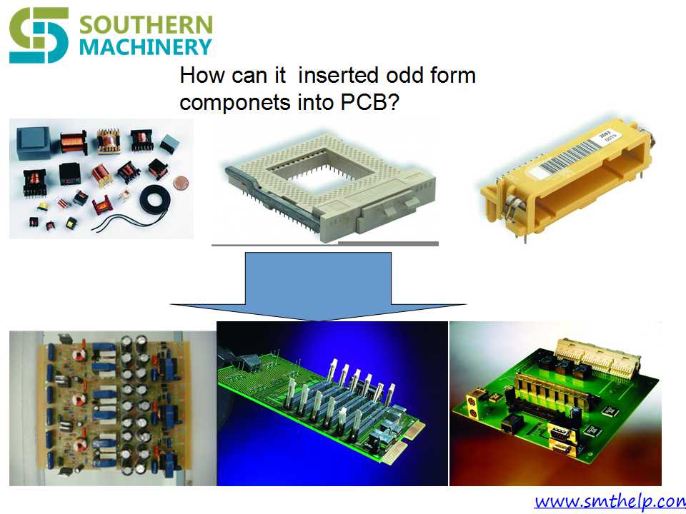
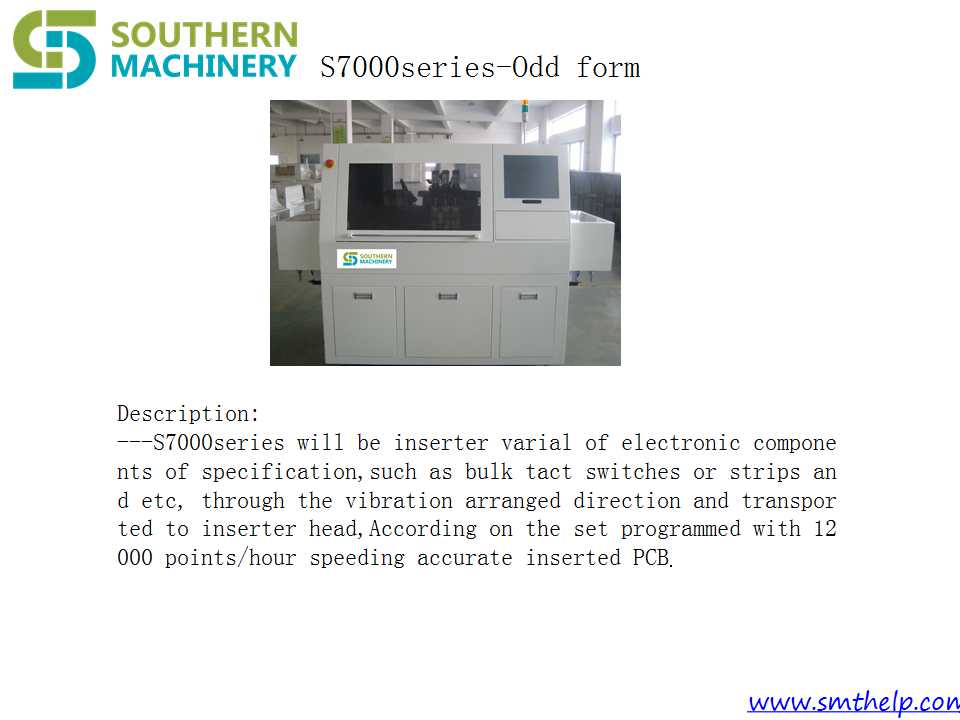
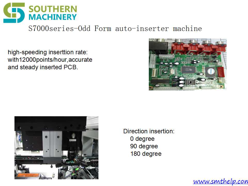
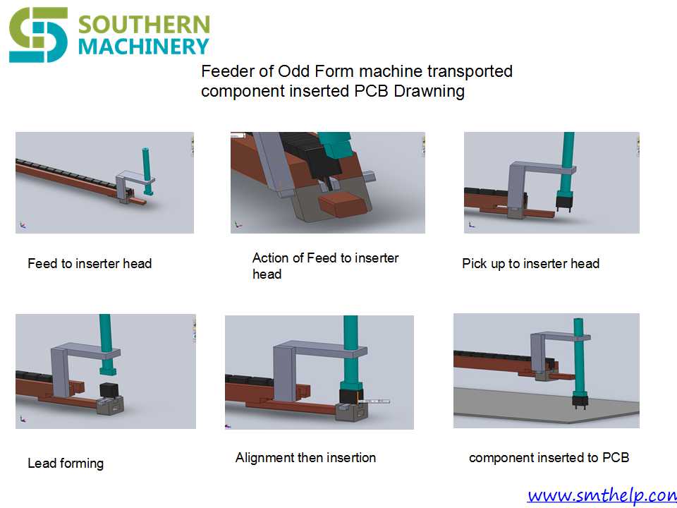
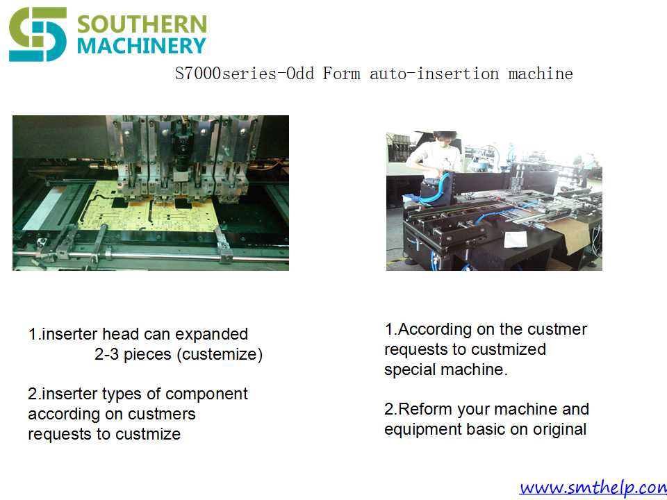
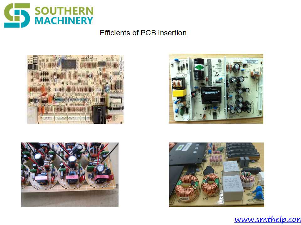
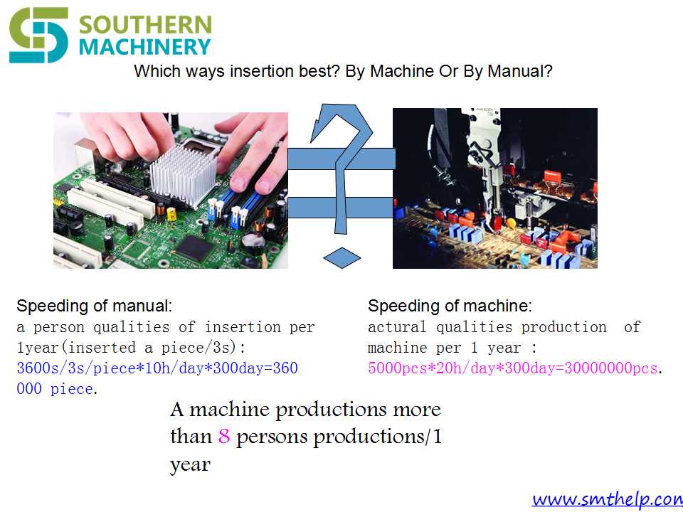
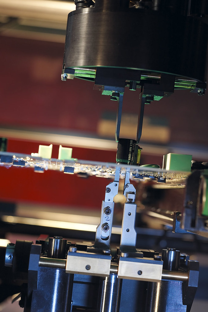
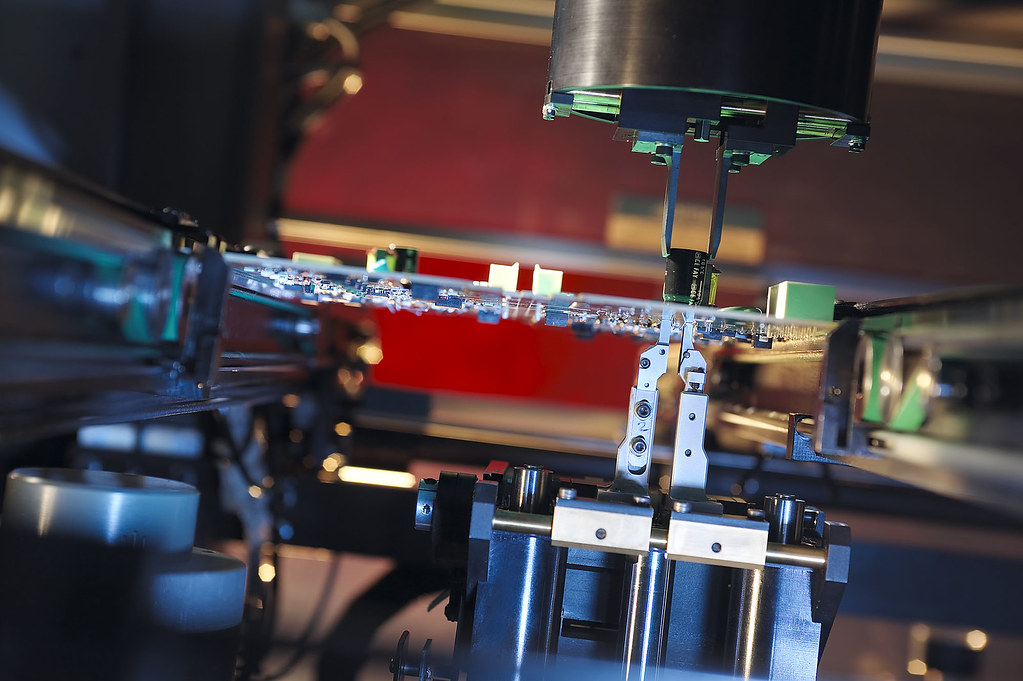
Odd form insertion
[embedyt]http://www.youtube.com/watch?v=4roGC7mdBIk[/embedyt]
