Auto Insertion machine Tooling Design vs. Range of Inserted Component Wire

1.0 INTRODUCTION

Do you have customers who are willing to simplify the Axial automated insertion process, speed up machines, lower preventative maintenance (pm) downtime and ppm levels and generally reduce manufacturing costs?  If so, then this paper may interest you.

Universal Instruments Corporation is currently working to customize tooling for customers who have evolved their manufacturing processes to two and three step processes for Axial insertions, thereby dedicating machines to run a limited range of components.  In step one for example, a machine inserts only 5mm insert spans and then in step 2, a second machine inserts various wire diameters.  This is a radical change from the current manufacturing philosophy of fully populating a board in one pass through a machine.  However, history has shown that by limiting the range of wire diameters inserted and then designing tooling to specifically handle that range, the manufacturing process becomes more controlled, insertion performance improves, pm downtime and ppm levels decrease and ultimately, manufacturing costs decrease.

Admittedly, this approach is not viable for every customer.  Universal offers a variety of tooling configurations that if used according to specification, will provide excellent insertion performance.  A customer may have no need to run a wide range of wire diameters or they may want to revisit their manufacturing process to make improvements.  For those customers, Universal offers customized tooling for dedicated applications.  Customized tooling will handle a limited range of wire diameters to optimize insertion performance and maximize tooling life.

This paper discusses the relationship between tooling design and  wire diameter range of inserted components with the goal of creating an awareness and understanding of this relationship and it’s significance.

2.0 FACTORS AFFECTING THIS RELATIONSHIP

2.1 Depth of V-Groove of Outside Former

One important factor affecting the relationship of tooling design and range of insertable wire diameters is the depth of the V-groove of the Outside Former.  Our current specifications for Axial tooling are as follows:

Standard

High Density

Large Lead

5mm

26mm AAA

Bottom View of Outside Former


Wire Diameter Range / Material

Steel:

.015”-.032”

(.39) – (.82)

Copper:

.015”-.032”

(.39) – (.82)

Steel:

.015”-.025”

(.39) – (.64)

Copper:

.015”-.032”

(.39) – .82)

Steel:

.025”-.032”

(.64) – (.82)

Copper:

.025”-.042”

(.64) – (1.01)

Steel:

.015”-.025”

(.39) – (.64)

Copper:

.015”-.028”

(.39) – (.72)

Steel:

.015”-.020”

(.39) – (.51)

Copper:

.015”-.024”(.39) – (.61)

Driver Tip Width

.030”

(.77)

.030”

(.77)

.050”

(1.27)

.017”*

(.44)

.012”*

(.31)

Metric equivalents are bracketed

* Not entire width but dimension from edge of Driver Tip to side of Outside Former

When the wire diameter is smaller than the depth of the V-groove of the Outside Former, the lead has excess space and moves within the V-groove.  This uncontrolled condition leads to a ‘weak’form. 


 V-groove with Small Lead Diameter

When the wire diameter is larger than the depth of the V-groove of the Outside Former, the yieldable Inside Former flexes to make room for the bigger lead.  Continual flexing causes the O-rings to wear out which leads to a ‘sloppy’Inside Former and ‘weak’forms.  Outside Formers have been known to split at the V-groove from continual stress.  Long term, continual flexing will damage the Tooling Housing by loosening it and making it ‘sloppy’.  


 V-groove with Large Lead Diameter

The optimal condition is wire diameter equal to the depth of the V-groove of the Outside Former.  In this condition, the lead is large enough so that is does not ‘move’within the V-groove, and yet it does not continually flex the Inside Former.


 V-groove with Optimal Lead Diameter

When Standard tooling is compared to 5mm tooling, it becomes clear why 5mm tooling is less reliable when inserting components with large lead diameters than Standard tooling.  

TOOLING

DEPTH OF V-GROOVE

WIRE DIAMETER RANGE

Standard

.028”(0.71mm)

.015”-.032”(0.39mm – 0.82mm).

5mm

.018”(0.46mm)

.015”- .028”(0.39mm – 0.72mm)

The depth of the V-grooves vary by .010”(0.26mm) and yet the range of wire diameter is very similar.

2.2 Radius of V-Groove of Outside Former

Another factor is the radius of the V-groove of the Outside Former.  The V-groove is actually a radius of .016”(0.41mm) for all tooling types except large lead tooling which is .019”(0.49mm).  Because this is a radius, not a diameter, the optimum lead size for this size radius is .032”(0.82mm)  This radius creates a situation that allows a small wire diameter to ‘roll around’or be uncontrolled in the groove.  A true V-groove improves this condition by creating a 2 point contact.  


One Point Contact

Two Point Contact


2.3 Body Length to Insertion Length

Body length to insertion length is another critical issue in this discussion.  The bigger the gap between the component body and the bend of the lead, the more room there is for the insertion tooling.  As the Driver Tip descends, it can damage a component body that is too long for the specified insertion span.  Clearance is also needed for the Inside Former coming beneath the bend of the lead.  A bend too close to the component body can also cause damage.  Maximum body length is obtained with the following formula: 

Programmed Z-Span = Insertion Span + 1 Lead Diameter

Maximum Body Length (clearance between Driver Tips)

= Insertion Span + 1 Lead Diameter – 2 x Depth of Outside Former V-groove – 2 x Driver Tip Thickness 

Do not use components with body lengths at the maximum length.  Allow .020”(0.51mm) on each side of a component body for clearance and to account for tolerances.


Component Body Leaving

Clearance

Component Body Leaving

No Clearance


2.4 Driver Tip Position

During a component insertion, the Driver Tip rests on the horizontal surface of the lead.  When a lead has a ‘weak’form, the Driver Tip rests on top of the bent portion of the lead.  As the Driver Tip tries to push a component through the holes of the pc board, it has a tendency to ‘slide off’a lead, leading to a standup or failed insertion.  This is true of 5mm tooling because of its small Driver Tip.


Driver Tip Position

during insertion

Driver Tip position during insertion 

of weak form lead


3.0 SUMMARY OF ABOVE CONDITIONS

· Wire diameters significantly smaller than the depth of the V-groove of the Outside Former are uncontrolled within the V-groove.  This is caused by one point contact and excess space, which leads to a ‘weak’form and poorly controlled insertion.  Small lead components without a ‘crisp’form are also at risk of misinserting because the Driver Tip may ‘slip off’the lead, while pushing it through the pc board.  This condition is seen most often with 5mm tooling.

· Wire diameters significantly larger than the depth of the V-groove of the Outside Former continually flex the yieldable, Inside Formers causing premature tooling wear-out of the Inside and Outside Formers as well as other parts of the tooling.

· Acceptable component body length varies with Z-span, but clearance is required for the Inside Formers and Driver Tips during insertion so the component body is not damaged. 

4.0 OPTIMAL CONDITIONS

To optimize insertion performance and maximize tooling life, it is best to limit the range of wire diameters inserted with any tooling selection, keeping in mind the optimal wire diameter is the same size as the V-groove of the Outside Former.  For example, if the wire diameter range of a particular application is .018”- .022”, a .020”V-groove is optimal.  This eliminates the problems mentioned above and allows optimal tooling life, process control and low insertion ppm.  

Making use of the squeeze function when writing pattern programs can also help.  If a component lead diameter is small in relation to the V-groove of the Outside Former, the squeeze function can improve a ‘weak’form.  The squeeze function is also useful when inserting steel leaded components as they tend to have a memory after the forming process.  It also helps insert components with long bodies and a small insertion span.

Allow clearance on each side of a component body so there is room for the insertion tooling.

Consider dedicating a manufacturing line to a particular application for optimal performance and then customize the tooling for a small range of wire diameters.  Universal offers customized tooling for dedicated applications.  Customized tooling can include the following items, as needed:

2 point contact in V-groove of Outside Former based on an optimum lead diameter

Increase size of Outside Former footprint for a more robust design

Improved bent lead input insertion capability

SMT,THT,PCB,PCBA,AI,wave soldering,reflow oven,nozzle,feeder,wave soldering,PCB Assembly, LED, LED lamp, LED display,

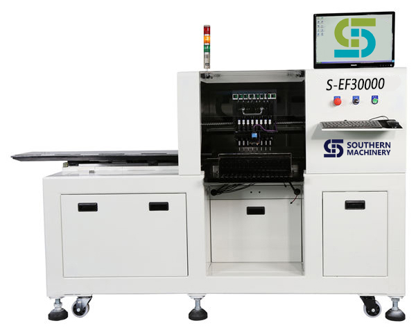
Southern Machinery LED SMT machine S-EF30000 vs Topaz XiII Comparision

Southern Machinery S-EF30000 vs Topaz XiII  Comparision
Model S-EF30000 Topaz XiII Result
No. Item (Southern Machinery Advantage)
1 Spec Speed 36,000 CPH 18,000 cph  double speed, double throughput
2 PCB Size Max: 1200×390mm Max: 460×440   Special design for 1.2m LED tube
3 flexible PCB yes, no need fixture need special make a fixture Suitable for flexible PCB strips
4 PCB loading Manual Approximately 3 sec. saving PCB loading time
5 Applicable components: 0603 to 7474 0201 – SOP, SOJ, PLCC 32mm Suitable for all LED lighting products
6 Machine Config 8 Spindles x 1 Gantry Simultaneous pick with 8  spindles
Fixed Vision Alignment System
8 Mounting accuracy:
(X,Y) 3σ
±0.05(3δ) ±0.10(6δ) chips ± 75µ for chips and SOIC totally enough for LED Chips
9 Mounting angle: 0 up to 360  0 up to 360 (in steps of 0.01)
10 Number of feeders: 16 (12mm) 8mm: 90 positions
11 Machine dimensions : 2,000(L) x 1,150(D) x 1,350(H) 1,650mm(L)x1,408mm(W)x1,850mm(H)
12 Machine weight: Approx. 950kg 1,600Kg
13 Maintenance Cost less $1000.00 per year  $2000.00 per year
14 Machine price $35,000.00  $70,000.00  at least saving 50% money
15 Performance / Price  1.03 (36000/35000) 0.26   (18000cph/$70000)
16 Conclusion: 5 times throughput / cost Advantage to use S-EF30000 produce LED product


SMT,THT,PCB,PCBA,AI,wave soldering,reflow oven,nozzle,feeder,wave soldering,PCB Assembly, LED, LED lamp, LED display, SMT,THT,PCB,PCBA,AI,wave soldering,reflow oven,nozzle,feeder,wave soldering,PCB Assembly, LED, LED lamp, LED display, SMT,THT,PCB,PCBA,AI,wave soldering,reflow oven,nozzle,feeder,wave soldering,PCB Assembly, LED, LED lamp, LED display,

How to gang place in LED pcb assembly

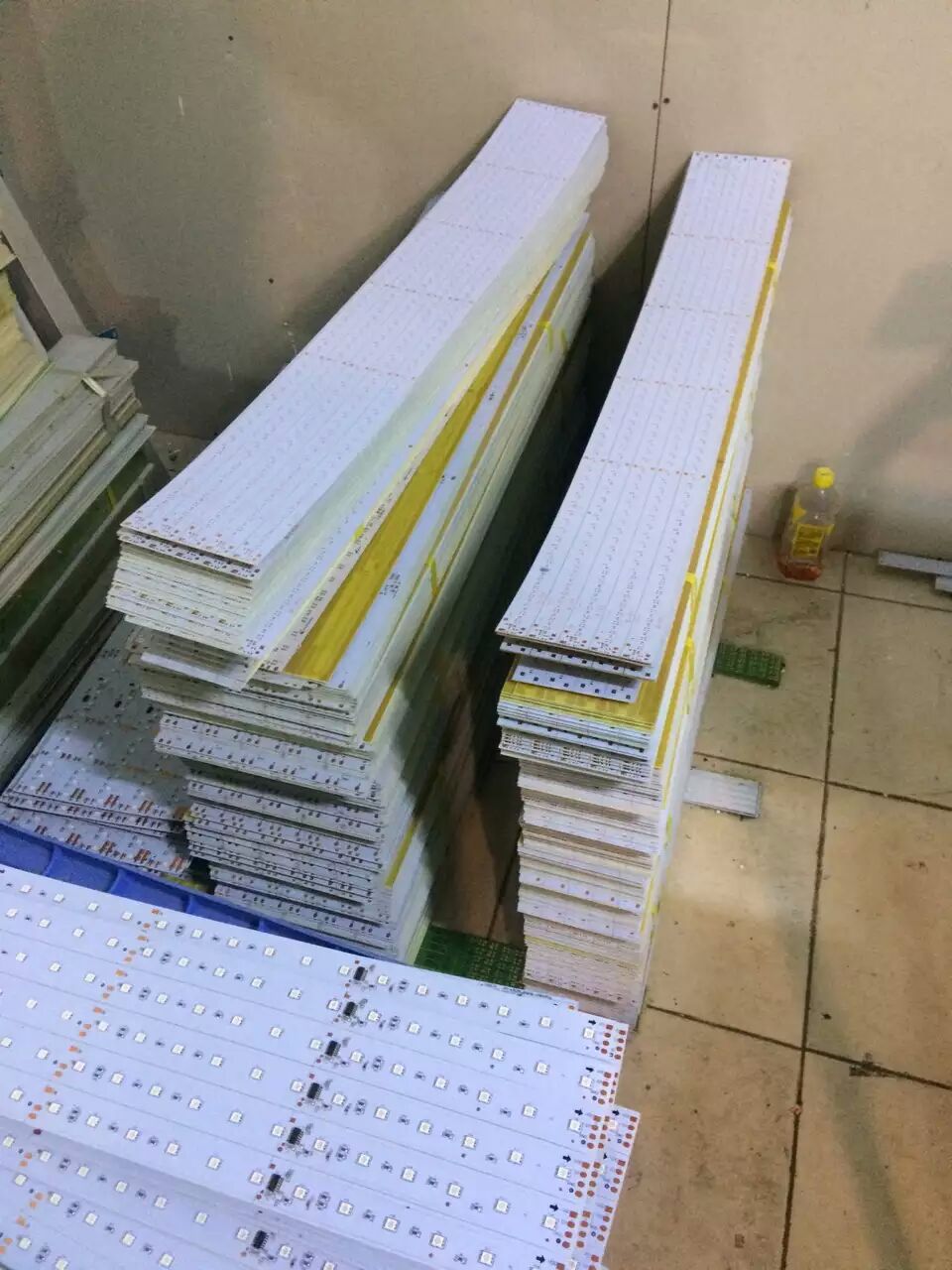
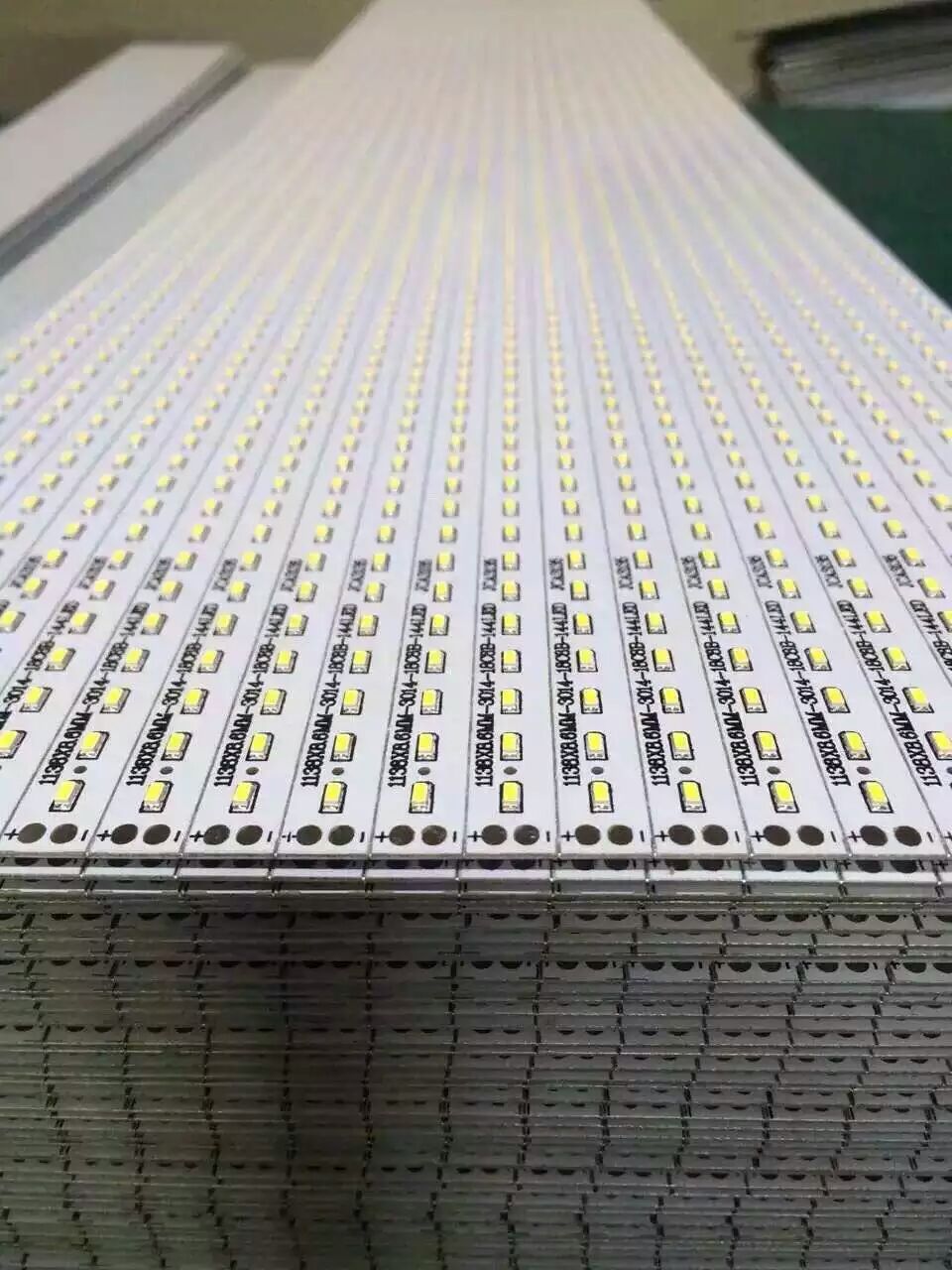
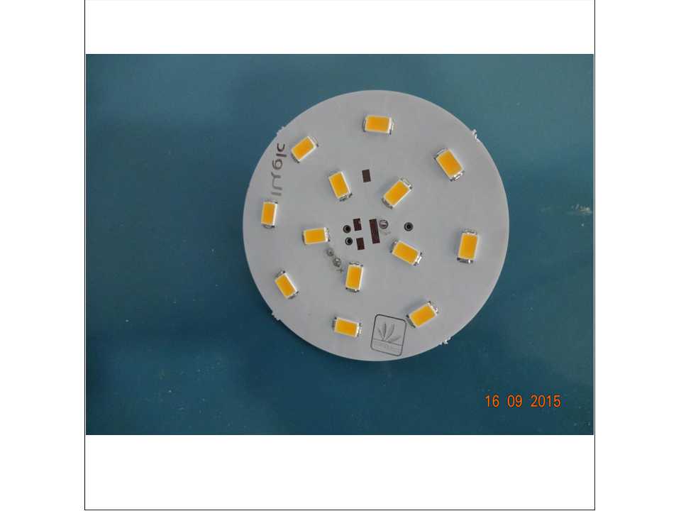
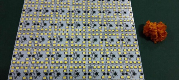
For cost-saving or technical reasons (such as improved assembly), multiple circuit boards may be combined to form one large board, a “panel”. This panel is then produced just as a single large http://bestacnedrug.com circuit board. Consult with us to design the distance of LED chips is same as the spindle distance of placement head.


SMT,THT,Auto Insertion,PCB,PCBA,wave soldering,stencil cleaner,LED,LED tube,LED bulb,LED dispaly,SMT nozzle,SMT feeder

SMT,THT,Auto Insertion,PCB,PCBA,wave soldering,stencil cleaner,LED,LED tube,LED bulb,LED dispaly,SMT nozzle,SMT feeder
OLYMPUS DIGITAL CAMERA
LED,PCB,SMT,PCBA,SMT,THT,PCB,PCBA,AI,wave soldering,reflow oven,nozzle,feeder,wave soldering,PCB Assembly, LED, LED lamp, LED display LED,SMT,THT,PCBA

SMT,THT,PCB,PCBA,AI,wave soldering,reflow oven,nozzle,feeder,wave soldering,PCB Assembly, LED, LED lamp, LED display,

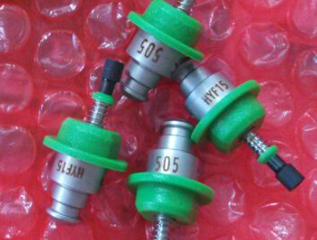
Why not Nozzle exchange for LED pick and place machine

1. As we consider that many customers products don’t have so many kinds of components in a board .

2. For example ,though in a board ,there are about 20 kinds of different components,but the size of many components are nearly . Sometimes just need about 3-4 kinds of nozzles is ok.

3. Besides, our S-EF30000 have 8 spindles, can install 8 kinds of different nozzles at a time,has mostly satisfied customers’ requirements of production , but also save machine’s cost for them .

4. As per your production ,if no need to install so many kinds of nozzles at a time and  change the nozzles automatically frequency , if we add a alternate pick up nozzle tray on our machine ,won’t it add your cost of the machine?

5. We won’t suggest you to buy our most expensive and with too many functions machine to increase your cost if your production no need. 


SMT,THT,PCB,PCBA,AI,wave soldering,reflow oven,nozzle,feeder,wave soldering,PCB Assembly, LED, LED lamp, LED display,

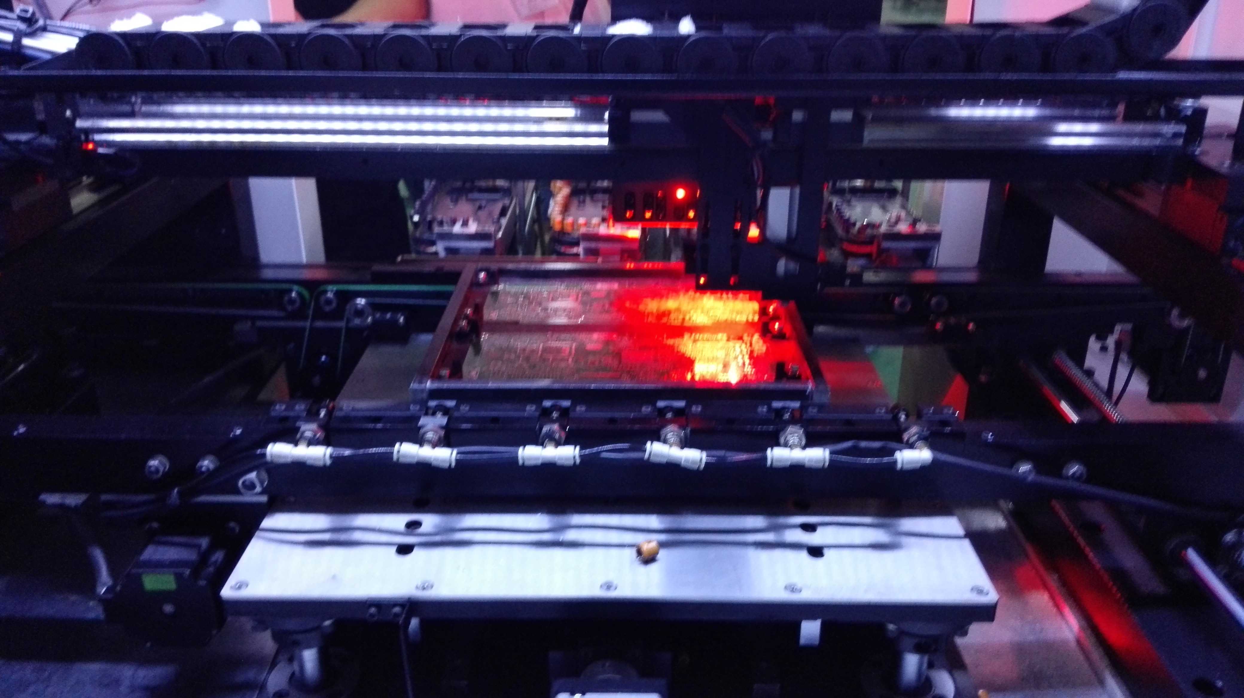
Vision System application for LED pick and place machine

1)Visual registration system 

(2) Laser detection registration system .

Both have different characteristics, so there are differences in the use.

Comparison:

Laser detection registration system:

Laser counterpoint to allow flight correction, capable of handling all shapes and sizes of components, and can accurately determine element position and direction, but, even more complex laser systems cannot measure the pin and pin spacing.

Visual registration system :

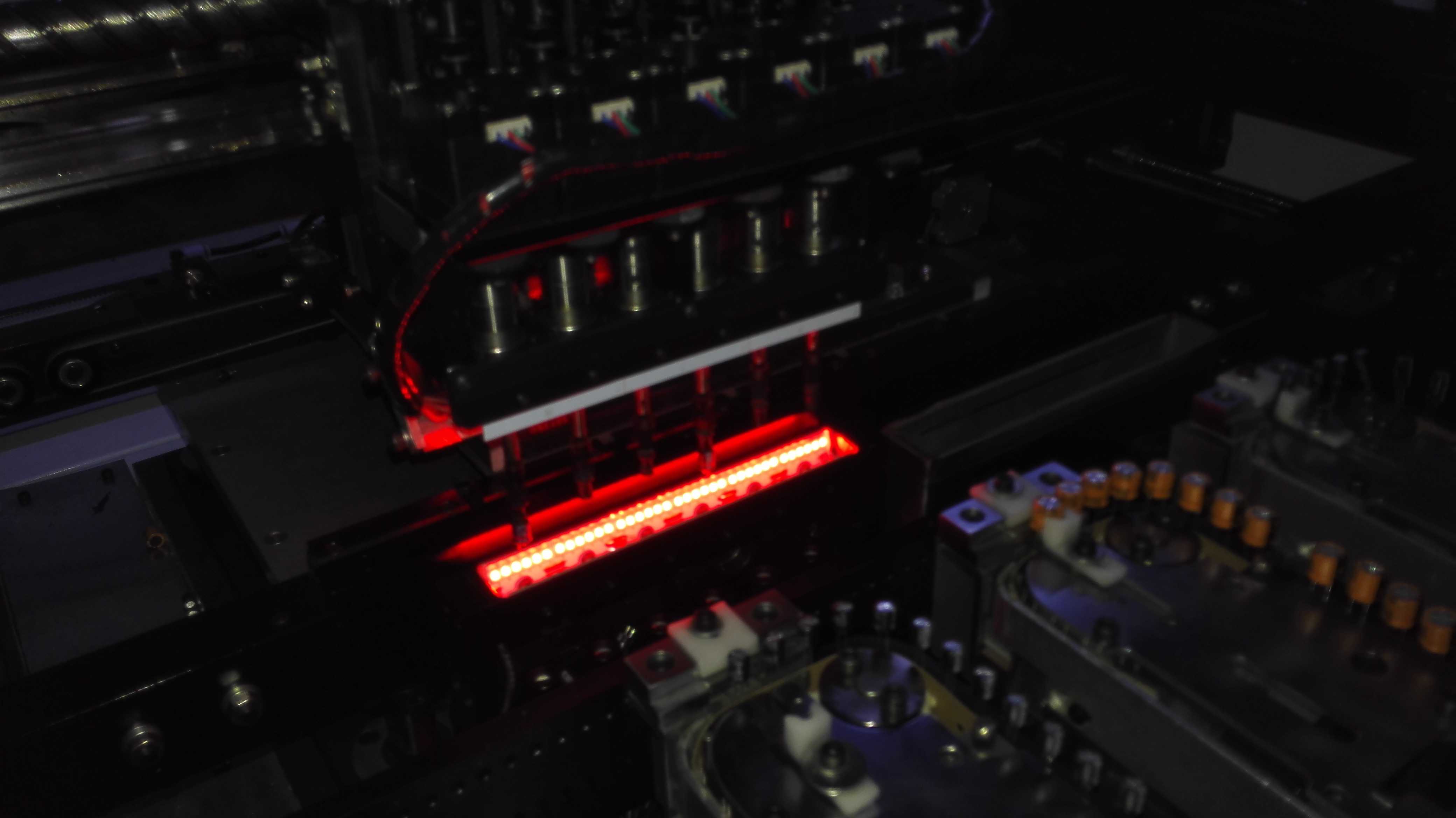
The visual system is able to judge the position and orientation of components and can  measure http://trueviagraonline.com lead and lead spacing at the same time .In addition, the visual system does not need to adjust the system will be able to adapt to the update components encapsulation, thus has better flexibility.

All of Southern machinery  the Pick & Place machine config with vision system 


SMT Radial Taped Feeder (23)

We provide spare parts for Panasert, Universal,TDK, Dynapert and Sciencgo Auto Insertion machine, SMT equipment. Worldwide 7x24 service online support
We provide spare parts for Panasert, Universal,TDK, Dynapert and Sciencgo Auto Insertion machine, SMT equipment.
Worldwide 7×24 service online support

SMT,THT,PCB,PCBA,AI,wave soldering,reflow oven,nozzle,feeder,wave soldering,PCB Assembly, LED, LED lamp, LED display,

$50000 SMT Line for LED Products Assembling


This line is designed specially for beginning manufacturers of LED lighting systems.

Special nature of LED systems production is the necessity to have high speed equipment for various LEDs and minimal set of SMD components.

The line is based on architecture of a standard line for SMD component assembly, but the equipment is modified specially for work with LEDs.


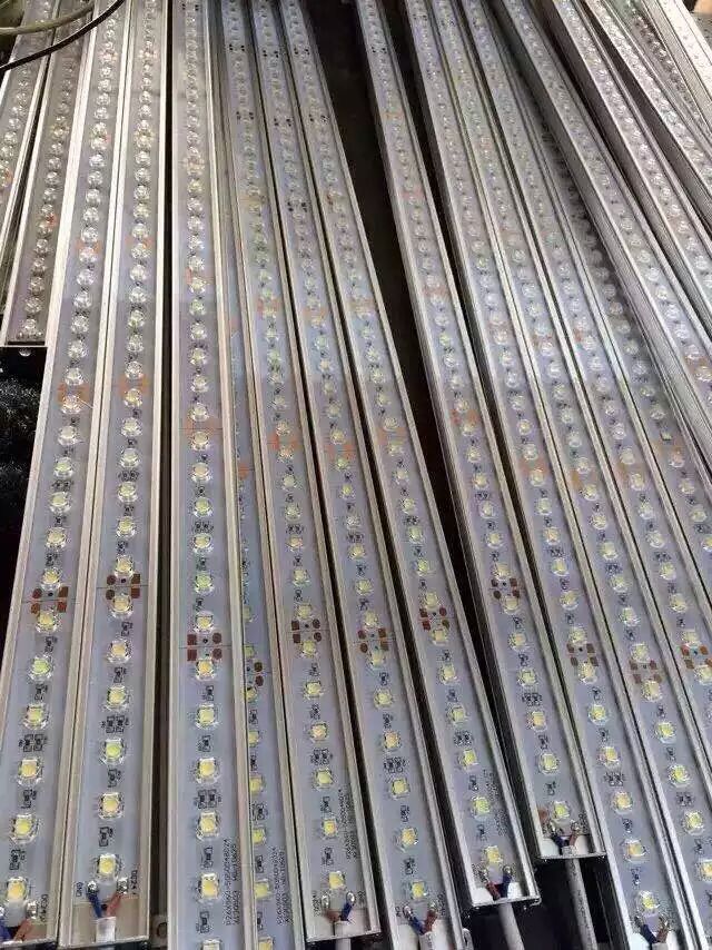
The oven length allows working with long aluminum PCBs (with high heat capacity) according to temperature profile recommended by LED vendor, without decreasing of operation time for the rest of the line.

Special vacuum nozzles are used for placing LEDs on PCBs; they are designed to avoid damage of their silicone lens. These nozzles are made of non-adhesive materials to avoid sticking of lens.

The unique ability of the line is work with LEDs in bulk; that could lower the cost of purchased components as well as the final cost of the product.


the photo below is one of our custmer

led line

Zuckerberg Responds To Critics, Explains How He’s Spending $45B

Zuckerberg Responds To Critics, Explains How He’s Spending $45B


 by Katie Roof 

On Tuesday, Facebook co-founder and CEO Mark Zuckerberg posted a powerful announcement — not only did he reveal the birth of his daughter, Max, but he shared plans to give up 99% of his personal Facebook shares over the course of his lifetime and use them to fund projects and causes through a newly formed entity called Chan Zuckerberg LLC.

The announcement generated a lot of attention, much of it due to the sheer volume of Zuckerberg’s net worth — $45 billion! While many people, including Bill Gates and Michael Bloomberg, praised him for his generosity, others expressed confusion and even questioned his motives for giving his money away.

Looking to alleviate some of those concerns, in a post Thursday,  Zuckerberg further explained how he and his wife Priscilla Chan, plan to delineate their funds.

“Our initial focus areas are personalized learning, curing disease, connecting people and building strong communities. We’ve already made many investments over the past five years in these areas — education, science, health, internet access and inclusion — and you can see a summary of our investments on the Chan Zuckerberg Initiative page timeline.”

Zuckerberg further addressed the allegations that this organization was a way to avoid taxes, and explained that by structuring the Chan Zuckerberg entity as an LLC, that their shares will still be taxed.

“By using an LLC instead of a traditional foundation, we receive no tax benefit from transferring our shares to the Chan Zuckerberg Initiative, but we gain flexibility to execute our mission more effectively. In fact, if we transferred our shares to a traditional foundation, then we would have received an immediate tax benefit, but by using an LLC we do not. And just like everyone else, we will pay capital gains taxes when our shares are sold by the LLC.”

He also says that this “for profit” structure allows them to make investments that will continue to fuel their objectives.

“This enables us to pursue our mission by funding non-profit organizations, making private investments and participating in policy debates — in each case with the goal of generating a positive impact in areas of great need. Any net profits from investments will also be used to advance this mission….For example, our education work has been funded through a non-profit organization,Startup:Education, the recently announced Breakthrough Energy Coalition will make private investments in clean energy, and we also fund public government efforts, like the CDC Ebola response and San Francisco General Hospital.”

Some of Zuckerberg’s early attempts at philanthropy were also met with controversy, particularly his $100 million gift to Newark schools.  But with $45 billion to experiment with, let’s hope that much of this money ends up doing a lot of good.

Zuckerberg previously signed The Giving Pledge, promising to give away over half his fortune, along with Richard Branson, Warren Buffett and other billionaires.

By timing the latest announcement with the birth of his baby, it seems that Zuckerberg is trying to send a message that he’s not hoarding his personal fortune for the next 100 generations of Zucks.

What is the high quality SMT machine

S-600-l mount machine from JianFeng Feng


 TOTAL SOLUTION FOR PCB AND LED ASSEMBLY – PROFESSIONAL SOLUTION OF SMT & AI.

     After years of effort,our products have been exported to many developing countries such as

 Brazil,Indonesia,Thailand,Saudi Arabia and Malaysia, during which time we have earned enormous good reputation.