How does SMT electronics assembly work?

Electronics manufacturing using surface-mount technology (SMT) simply means that electronic components are assembled with automated machines that place components on the surface of a board (printed circuit board, PCB).

SMT车间

Electronics manufacturing using surface-mount technology (SMT) simply means that electronic components are assembled with automated machines that place components on the surface of a board (printed circuit board, PCB). In contrast to conventional through-hole technology (THT) processes, SMT components are placed directly on the surface of a PCB instead of being soldered to a wire lead. When it comes to electronic assembly, SMT is the most frequently used process in the industry.

Electronic assembly encompasses not only placing and soldering components to the PCB, but also the following production steps:

  • Applying soldering paste, which is made of tin particles and flux, to the PCB
  • Placing SMT components to the soldering paste on the PCB
  • Soldering the boards with a reflow process.

Applying Soldering Paste

Applying soldering paste is one of the first steps in the SMT assembly process. Soldering paste is “printed” on the boards using the silk-screen method. Depending on the design of the board, different stainless-steel stencils for “printing” the paste onto the board and various product-specific pastes are used. Using a laser cut stainless-steel stencil custom made for the project, the soldering paste to be applied only to the areas where components will be soldered. After the soldering paste is on the boards, a 2D-soldering paste inspection is performed to ensure that the paste is evenly and correctly applied. Once the accuracy of the soldering paste application has been confirmed, the boards are transferred to the SMT assembly line, where the components will be soldered.

AI spare parts、Universal Parts,UIC,TDK.VCD Sequencer.SMT,THT,PCB,PCBA,AI,wave soldering,reflow oven,nozzle,feeder,wave soldering,PCB Assembly, LED, LED lamp, LED display AI spare parts、Universal Parts,UIC,TDK.VCD Sequencer.SMT,THT,PCB,PCBA,AI,wave soldering,reflow oven,nozzle,feeder,wave soldering,PCB Assembly, LED, LED lamp, LED display

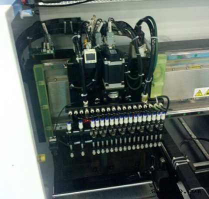
Component  Placement and Assembly

The electronic components to be assembled come in trays or reels, which are then loaded into the SMT machine. During the loading process, intelligent software systems ensure that components are not inadvertently switched or misloaded. The SMT assembly machine then automatically removes each component with a vacuum pipette from its tray or reel and places it on its correct position on the board using precise pre-programmed X-Y coordinates. Our machines are capable of assembling up to 25,000 components per hour. After the SMT assembly is completed, the boards are moved on to the Reflow ovens for soldering, which affixes the components to the board.

S-320 pick&place machine

SMT line

Component Soldering

To solder electronic components, we use two different methods, each of which has distinct advantages depending on the order quantity. For series production orders, the Reflow-soldering process is used. During this process, boards are put in a nitrogen atmosphere and are gradually warmed up with heated air until the soldering paste melts and the flux vaporizes, which fuses the components to the PCB. After this stage, the boards are cooled off. As the tin in the soldering paste hardens, the components become permanently affixed to the board and the SMT assembly process is completed.

For prototypes or highly sensitive components, we have a specialized vapor-phase soldering process. In this process, boards are heated until the specific melting point (Galden) of the soldering paste is reached. This allows us to solder at lower temperatures or solder different SMT components at different temperatures depending on their individual soldering temperature profiles.

PastedGraphic-59

AOI and Visual Check

Soldering is the second-to-last step of the SMT assembly process. In order to ensure the quality of the assembled boards, or to catch and correct a mistake, AOI visual inspections are performed for almost all series production orders. Using several cameras, the AOI system automatically checks each board and compares the appearance of each board with the correct, pre-defined reference image. If there are any deviations, the operator of the machine is informed of the potential problem, who then corrects the mistake or pulls the board from the machine for further inspection. The AOI visual check ensures consistency and accuracy in the SMT assembly production process.

Dimensons_floor _layout - A_cmyk

S600-OF SERIES AUTO INSERT&SURFACE MOUNTING MACHINE

S600-OF SERIES

AUTO INSERT&SURFACE MOUNTING MACHINE

The s-600-of is a revolutionary new concept from southern machinery.
that allows the placement or insertion of both http://tadalafiltablets.net surface mount
and through-hole components.

Nozzle: 6 PCS
?PCB Size:400*360mm
?Speed:12000-15000CPH

?Insert Object:Capacitor,Switch,
Connector, etc.
?Mounting Objet:Standard SMD
CLICK HERE TO SEND ME A EMAIL

AI, Auto Insertion : Axial Inserter; Radial Inserter; JW (Jumper Wire) Inserter; Odd form Inserter; PIN inserter; Eyelet Inserter; Terminal Inserter IM, Insertion Mount, MI,Manual Insertion, DIP, Wave soldering 5, SMT - Souface Mount Technology: BHS: PCB board handling system, Loader, Unloader, Conveyor,Shuttle Printer: Solder paste screen printer SPI: Solder Paste Inspection Mounter: Chip Mounter, Pick and Place, IC Mounter, High Speed Mounter AOI Reflow Oven

Auto Insertion machine CPU board EPC-1316 Boot Sector and BIOS Corruption Procedure for Re-flash

48797301 board
Procedure

Symptoms of corrupted BIOS and/or Boot Block:

  • No video signal from the EPC-1316
  • No activity on
  1. The keyboard, no status lights at power-on
  2. The floppy drive with a disk in or out
  3. The hard disk drive evident by the light off after a certain amount of time
  • The EPC-1316 is trying to access the CD-ROM drive with failed attempts every second or so.
  • The EPC-1316 is in this cycle indefinitely

Steps to take:

  1. Power down the EPC-1316 board/machine.
  2. Make sure that this instructions file is opened on a different computer.
  3. At the last step of these instructions is an embedded object of the .zip folder; it contains all of the files needed for this procedure.
  4. Right click on the .zip folder, select ‘Package Object’ and click on ‘Activate Contents’. If a message regarding a trustworthy source is displayed, confirm that this source can be trusted
  5. Create a new folder on the Desktop and rename it to “EPC-16FBD1.00.10”
  6. Click ‘File’, then select and click on ‘Extract All…’
  7. Extract the .zip folder into the folder on the Desktop, created in Step 3.
  8. Obtain a 3.5in Floppy Disk and insert it into the drive.
  9. Open the “EPC-16FBD1.00.10” folder from the Desktop
  10. To run an MS-DOS program, double click on the CRISDISK.BAT file.
  11. To run a Windows Application, double click on the WINCRIS.EXE file.
  12. Go through prompts of the program attentively; and a crisis disk will be created.
  13. Remove the EPC-16 board from the VME chassis/rack.
  14. At the bottom of the board there are 2 x 5 jumper pins: MFG/Flash. (Figure 1)


Figure 1 EPC-1316 Board jumper pin location

  1. See Figure 2 for PIN-out of the Jumper pins.


Figure 2 EPC-1316 Board jumper pin numbering

  1. Using 2 jumpers (Figure 3): place one to jumper pins 4-6. (jumper setting ‘Write Boot Block’)
  2. Place the second to jumper pins 3-5. (jumper setting ‘Force flash recovery’)


Figure 3 EPC-1316 Board flash jumpers configuration

  1. Replace the EPC-1316 board to the VME chassis/rack.
  2. Insert the 3.5in Floppy Disk that was created from the steps above into the floppy drive.
  3. Power-up the machine/chassis/EPC-1316.
  4. If the status light on the floppy drive comes on and stays on, then the floppy disk is being accessed.
  5. When the floppy drive stops accessing the Floppy Disk, wait about 5 seconds, and then remove the disk.
  6. Power down the EPC-1316, and remove it from the VME interface.
  7. Remove jumpers from the board and replace the board to the VME interface.
  8. Power-up the machine/chassis/EPC-1316 and make sure that it boots the operating system.
  9. Refer to UIC procedures for proper BIOS settings/ configuration


UIC, EPC-1316 Boot Sector and BIOS Corruption Procedure for Re-flash

Procedure

Symptoms of corrupted BIOS and/or Boot Block:

  • No video signal from the EPC-1316
  • No activity on
  1. The keyboard, no status lights at power-on
  2. The floppy drive with a disk in or out
  3. The hard disk drive evident by the light off after a certain amount of time
  • The EPC-1316 is trying to access the CD-ROM drive with failed attempts every second or so.
  • The EPC-1316 is in this cycle indefinitely

Steps to take:

    1. Power down the EPC-1316 board/machine.
    2. Make sure that this instructions file is opened on a different computer.
    3. At the last step of these instructions is an embedded object of the .zip folder; it contains all of the files needed for this procedure.
    4. Right click on the .zip folder, select ‘Package Object’ and click on ‘Activate Contents’.  If a message regarding a trustworthy source is displayed, confirm that this source can be trusted
    5. Create a new folder on the Desktop and rename it to “EPC-16FBD1.00.10”
    6. Click ‘File’, then select and click on ‘Extract All…’
    7. Extract the .zip folder into the folder on the Desktop, created in Step 3.
    8. Obtain a 3.5in Floppy Disk and insert it into the drive.
    9. Open the “EPC-16FBD1.00.10” folder from the Desktop
    10. To run an MS-DOS program, double click on the CRISDISK.BAT file.
    11. To run a Windows Application, double click on the WINCRIS.EXE file.
    12. Go through prompts of the program attentively; and a crisis disk will be created.
    13. Remove the EPC-16 board from the VME chassis/rack.
    14. At the bottom of the board there are 2 x 5 jumper pins: MFG/Flash. (Figure 1)

Figure 1 EPC-1316 Board jumper pin location

    1. See Figure 2 for PIN-out of the Jumper pins.


Figure 2 EPC-1316 Board jumper pin numbering

    1. Using 2 jumpers (Figure 3): place one to jumper pins 4-6. (jumper setting ‘Write Boot Block’)
    2. Place the second to jumper pins 3-5. (jumper setting ‘Force flash recovery’)

Figure 3 EPC-1316 Board flash jumpers configuration

    1. Replace the EPC-1316 board to the VME chassis/rack.
    2. Insert the 3.5in Floppy Disk that was created from the steps above into the floppy drive.
    3. Power-up the machine/chassis/EPC-1316.
    4. If the status light on the floppy drive comes on and stays on, then the floppy disk is being accessed.
    5. When the floppy drive stops accessing the Floppy Disk, wait about 5 seconds, and then remove the disk.
    6. Power down the EPC-1316, and remove it from the VME interface.
    7. Remove jumpers from the board and replace the board to the VME interface.
    8. Power-up the machine/chassis/EPC-1316 and make sure that it boots the operating system.
    9. Refer to UIC procedures for proper BIOS settings/ configuration


One Video show you China Made LED chips SMT pick and place machine

2015 new designed LED light board pick and place assemble machine   :

Mounting head: Double arm, 36 pieces sucking mouth, 18 pieces sucking mouth per arm

Min mounting distance: 13.5mm

Driving motor of mounting head(Y axis): Principle motor(magnetic), 15% faster than servo screw motor

Mounting range: 0805,1206,2121,2835,3014,3528,5050,5630,5730,RGB and other LED belt light

Theory mounting speed: 70K CPH*2=140K CPH

Working mounting speed: 60K CPH*2=120K CPH

PCB sizes:1200MM(L)-300MM(W)

Feeder amount: 18 feeder(8mm)*2=36 feeders,electronic feeder

Vibrating disc, for bulk material: Can be customized, vibrating disc can be changed with FEEDER, and the

working speed is the same

Dimension(L*W*H): 2650*1650*1350mm

Total weight: 2000kg

Application: 0.3-1.2 meter LED daylight tube and soft light belt include RGB strip light, LED panel light etc


Model Pick and place speed Overall sizes( L*W*H) Weight
S-K100 Belt LED SMD 120K CPH 2650*1650*1350mm 2000kg
S-K200 Belt LED SMD 180K CPH 2650*1750*1400mm 2500kg
S-K100VP Bulk LED SMD 80K CPH 2650*1650*1350mm 2000kg
Detailed Images

Fully automatic electric feeder, can set the feeding design according to your mounting needs through the computer:

The highest capacity LED light board pick and place assemble machine


Double module mounting head, each module has 16 pieces sucking head:

The highest capacity LED light board pick and place assemble machine


South Korea magnetic motor, guarantee high mounting speed, easy to maintain:

The highest capacity LED light board pick and place assemble machine


Top performance industry computer, can be folded into the machine, easy to set placing design:

The highest capacity LED light board pick and place assemble machine


Skoda alarm, let you know the pick and place machines working condition clearly:

The highest capacity LED light board pick and place assemble machine


AI spare parts、Universal Parts,UIC,TDK.VCD Sequencer.SMT,THT,PCB,PCBA,AI,wave soldering,reflow oven,nozzle,feeder,wave soldering,PCB Assembly, LED, LED lamp, LED display,

SMT Pick And Place machine Spare parts

We can supply smt machine parts, smt spare parts, replacement parts for pick and place machine, Brands including FUJI, SIEMENS, PANASONIC, JUKI, YAMAHA, , etc.


Part of product list: 

Compatible for

Part name

Part No.

Usage

fuji NXT H01

H01 Filter (with plastic BKT)

AA1FZ01

Consumable parts

fuji NXT H12

H12 Filter (with plastic BKT)

AA19H02

Consumable parts

fuji NXT H01

H01 smt filter

XH00560

Consumable parts

fuji

smt pin thick pin

ADCQK8010

replacement parts

fuji

smt pin thin pin

ADCQK8010

replacement parts

fuji XP243

XP243 U axis PULLEY

AGFTR8220

replacement parts

fuji XP243

XP243 U axis PULLEY

AGFTR8230

replacement parts

fuji

fuji sliding block and thimble

O0186

replacement parts

fuji CP6

CP6 HOLDER

AWPH3110

replacement parts

fuji CP43

CP43 CLUTCH

MPH0501

replacement parts

fuji QP242

QP242 Filter

H3022T

Consumable parts

fuji CP41

CP41 press button

O0191

replacement parts

fuji IP3

IP3 Filter

H30215

Consumable parts

fuji CP6

cylinder

WPA5150

Consumable parts

fuji CP7 CP8

smt filter

DCPH3780

Consumable parts


AI spare parts、Universal Parts,UIC,TDK.VCD Sequencer.SMT,THT,PCB,PCBA,AI,wave soldering,reflow oven,nozzle,feeder,wave soldering,PCB Assembly, LED, LED lamp, LED display,
H10212
angela@smthelp.net

AI spare parts、Universal Parts,UIC,TDK.VCD Sequencer.SMT,THT,PCB,PCBA,AI,wave soldering,reflow oven,nozzle,feeder,wave soldering,PCB Assembly, LED, LED lamp, LED display,
H13362
angela@smthelp.net

AI spare parts、Universal Parts,UIC,TDK.VCD Sequencer.SMT,THT,PCB,PCBA,AI,wave soldering,reflow oven,nozzle,feeder,wave soldering,PCB Assembly, LED, LED lamp, LED display,
H30105
angela@smthelp.net

AI spare parts、Universal Parts,UIC,TDK.VCD Sequencer.SMT,THT,PCB,PCBA,AI,wave soldering,reflow oven,nozzle,feeder,wave soldering,PCB Assembly, LED, LED lamp, LED display,
H42693
angela@smthelp.net

AI spare parts、Universal Parts,UIC,TDK.VCD Sequencer.SMT,THT,PCB,PCBA,AI,wave soldering,reflow oven,nozzle,feeder,wave soldering,PCB Assembly, LED, LED lamp, LED display,
K1006L COUPLING
angela@smthelpl.com

AI spare parts、Universal Parts,UIC,TDK.VCD Sequencer.SMT,THT,PCB,PCBA,AI,wave soldering,reflow oven,nozzle,feeder,wave soldering,PCB Assembly, LED, LED lamp, LED display,
H3022T
angela@smthelp.net

AI spare parts、Universal Parts,UIC,TDK.VCD Sequencer.SMT,THT,PCB,PCBA,AI,wave soldering,reflow oven,nozzle,feeder,wave soldering,PCB Assembly, LED, LED lamp, LED display,
H3022L
angela@smthelp.net

AI spare parts、Universal Parts,UIC,TDK.VCD Sequencer.SMT,THT,PCB,PCBA,AI,wave soldering,reflow oven,nozzle,feeder,wave soldering,PCB Assembly, LED, LED lamp, LED display,
H2002Y
angela@smthelp.net

AI spare parts、Universal Parts,UIC,TDK.VCD Sequencer.SMT,THT,PCB,PCBA,AI,wave soldering,reflow oven,nozzle,feeder,wave soldering,PCB Assembly, LED, LED lamp, LED display,
GFPH2540
angela@smthelp.net

AI spare parts、Universal Parts,UIC,TDK.VCD Sequencer.SMT,THT,PCB,PCBA,AI,wave soldering,reflow oven,nozzle,feeder,wave soldering,PCB Assembly, LED, LED lamp, LED display,
GFPN1160
angela@smthelp.net

AI spare parts、Universal Parts,UIC,TDK.VCD Sequencer.SMT,THT,PCB,PCBA,AI,wave soldering,reflow oven,nozzle,feeder,wave soldering,PCB Assembly, LED, LED lamp, LED display,
H1124D
angela@smthelp.net

AI spare parts、Universal Parts,UIC,TDK.VCD Sequencer.SMT,THT,PCB,PCBA,AI,wave soldering,reflow oven,nozzle,feeder,wave soldering,PCB Assembly, LED, LED lamp, LED display,
A10397
angela@smthelp.net

AI spare parts、Universal Parts,UIC,TDK.VCD Sequencer.SMT,THT,PCB,PCBA,AI,wave soldering,reflow oven,nozzle,feeder,wave soldering,PCB Assembly, LED, LED lamp, LED display,
2MGKCF001600
angela@smthelp.net
XS01802=XS03693 SPOOL NXT 原装全新..

SMT and Auto Insertion Machine Critical 1 Spare Parts Definition

Critical 1 Spare Parts Definition

What are Critical 1 Spare Parts?

Critical 1 (C1) parts are parts that may fail with no warning, may not show signs of wear, or may cause other parts to fail.  They cause a machine failure with no work around.  These are the parts that most concern our customers as their failure can stop a production line.  

C1 parts are identified by engineering and product support teams during the product development/introduction process.  

C1 lists are generated and tracked as part of the development cycle and are made available prior to shipments of production volumes to customers.

As a guideline C1 parts will not be duplicated in RPKs.  There may be exceptions that will require cross functional agreement.  

What is NOT typically considered a Critical 1 Spare Part:

Consumables or wear parts

High usage spares

Exceptionally robust parts or assemblies

General Hardware (typically) 

What is the key difference between Critical 1 and Replacement Parts Kits (RPK)?

Replacement parts kits (RPK) include items customers are expected to need within 6 months of use.  Examples of parts in the RPK includes consumables items, wearable parts and predictable failures.  

Typical RPK items:

Fuses

Light bulbs

Belts 

Wearable tooling

Hardware associated with general maintenance

AI spare parts、Universal Parts,UIC,TDK.VCD

FREQUENTLY ASKED S-K100 High Speed LED PICK & PLACE MACHINE QUESTIONS AND ANSWERS

1)What is high speed led tube and led strip pick and place machine ?

The high speed automatic SMT mounting machine is the equipment used to realize high-speed, high accuracy completely automatic mounting the electric elements like LED light sphere, electric resistance , electric capacity etc. It is the mot essential and most complex equipment in the entire SMT production. The mounting machine is the major machine in SMT production line, and it is already developed from the early low speed mechanical mounting machine to high-speed optics mounting machine, and to multipurpose, flexible connection modulation development.


2)What machines does the LED PCB board assembly need ?

The LED mount technical process simplification is: Printing, Pick and placing, Soldering, Overhaul (in each part, you can join examine link to control quality)


3) What are the advantages of Langke smd pick and place machine?

A.Top high speed in the world, quicker than the main SMT pick and place machines brands like Siemens, Fuji, Samsung, Panasonic, Sanyo and Juki led pcb pick and place machines;

B.Lowest power consumption, 2.5-3.5KW/Hour, our machine has the smallest electricity consumption among the high speed pcb pick and place machine manufacturers in China

C.Match vacuum pumps along with the main machine, no need to match extra vacuum pump;

D.Electric control system is installed on the top of the main machine, easy to maintain, and has a good damp proof effect;

E.Integrated forming steel frame, guarantee stable performance on high speed running conditions.

F.The distance of sucking mouth can be adjusted manually, photoelectric will make sure the accuracy after adjust, allow you to mount different pitches PCB board.


4) What kinds electric components can use our automatic led smt pick and place assembling machine!

The main elements our machine can mount include: LED lights, electric capacity and electric resistance, sizes like: 0805,1206,2121,2835,3014,3528,5050,5630,5730,RGB; mainly for 1.2-1.5 meter LED light tube, LED panel light, 0.5-1.0 meter LED light strip , RGB strip.

Quality Control for Auto Insertion machine manufacturing


Quality Control


Every Auto Insertionl machine
is subjected to a Quality Acceptance Test (QAT) before being shipped to
its customer. There are 4 phases to a QAT:


Phase I – Pre-Dry Cycle


The
appropriate pattern program is loaded and the machine performs a short
part run with all motions and mechanisms functioning to check setups and
speed. All data is recorded on the machine’s event log.


Phase II – Dry Cycle


Can
only occur after successful completion of the Pre-Dry Cycle. The
machine is run with all motions and mechanisms functioning but without
boards or inserting components for a pre-specified period of time. All
data is recorded on the machine’s event log.


Phase III – Integrity Run (Final Run)


Can
only occur after successful completion of the Dry Cycle. This is a
simulated production run to check insertion performance and speed.
Results are recorded on the machine’s event log.


Axial Inserter

S4000

Radial Inserter

S3000

Phase I


Parts Run

2000

2000

Insertion PPM *

0

0

Intrinsic Availability **

100%

100%

Phase II


Length of Run

12 hrs.

12 hrs.

Intrinsic Availability

95%

95%

Phase III


Minimum Parts Run

20000

20000

Allowable Insert Errors

10

20

Intrinsic Availability

95%

95%

Acceptable PPM Levels

500 – 1000

1000

Confidence Level

95%

95%


* (# of good insertions / total # of insertions)

** (# of hours the machine is ready to run / total # of hours machine planned to run)


Phase IV – Customer Acceptance (Optional)


Can
only occur after successful completion of the Integrity Run. The
customer visits the factory to watch verify the machine’s ability to
meet performance requirements. The customer’s production run is
simulated and all options are verified and explained. 


 For any further questions regarding the customer acceptance procedure, please  contact:


 Albert Wen

 Albert@smthelp.net


Phase V – Preproduction Acceptance (At customer site)


Service engineer installs the machine and assures it is setup
and running with the same degree of operational efficiency as at the
factory.