PCB Board handling system in Smart factory

The Southern Machinery is a Shenzhen-based company, providing professional automatic insertion machines tailor-made for Electronic Manufacturing Factory. Our team works with recognized experts that have many years of working experience in the industry.

As an industry leader with over 20 years of experience in electronic manufacturing, we provide comprehensive guidance from the AI / PCB design (DFM), AIprocess (NPI) to equipment importing, installation, and auto insertion technology (THT) training, machine troubleshooting/ upgrading/ overhauling / relocating/ fittings. We also offer an affordable line-up of all brand spare parts.
By saving your time and money through getting your PCB Assembly automated, your long-term return on invest (ROI) will also increase http://your-pharmacies.com with producing PCBs in-house. Working with a proven industry leader allows you to focus on your core business with PCB assembly handled by the proven specialists at Southern Machinery.
We are committed to conducting any level of EMS design work and providing electronic design services. These value-added design services can verify the accuracy and precision of electronic designs, leading to significant improvements for production output and resulting in superior products with higher quality that your target market will love.

[Canvasio3DPro templateID=”13″ objectID=”14″][/Canvasio3DPro]


[Canvasio3DPro templateID=”14″ objectID=”15″][/Canvasio3DPro]


[Canvasio3DPro templateID=”14″ objectID=”16″][/Canvasio3DPro]


[Canvasio3DPro templateID=”14″ objectID=”17″][/Canvasio3DPro]

How SMT solder paste is mixed. Is there any quick way?

How SMT solder paste is mixed. Is there any quick way?

The solder paste should be fully stirred before using
Purpose: To make the flux and tin powder evenly distributed, give full play to various characteristics;
Mixing method: manual mixing or machine mixing can be; mixing time: manual: about 4 minutes machine: 1 ~ 3 minutes
1) Manual Mixing: Remove the solder paste from the freezer and open the cover until it returns to room temperature (about three to four hours at 25 ° C). Stir the solder paste with a stirring knife. If the cover is broken, tin The cream will become tin pieces by absorbing moisture.
2) with automatic mixer:. If the solder paste is removed from the freezer, there is only a brief warm-up period and you will need to use an automatic mixer to use automatic mixing without affecting the solder paste characteristics. After a period of agitation, the solder paste will. Gradual warm-up If the mixing time is too long, it may cause the solder paste to be higher than the operating room temperature, causing the solder paste to be poured over the board in one piece, and flow (bleeding) during printing, so be careful. Due to different machines, room temperature and other conditions change, will result in different mixing time, so before proceeding, please prepare enough test.
Stirring effect of the judge: Scraping part of the solder paste with a scraper blade tilt, if the solder paste can slide down smoothly, that is, the right to meet the requirements of the appropriate mixing time due to the mixing method, the device and the ambient temperature and other factors vary, should Do more experiments in advance to determine.

We have a fully automatic tin paste mixer which can solve these problems:

Solder Paste Mixer

automatic solder paste mixer for SMT production , this solder paste mixer , mix the solder paste when SMT production before solder paste printer .

Solder Paste Mixer-1

 the machine features Features:    

 1. 0 speed can reach 1000 rpm     

1.1 Solder Paste not need to first thaw stirring;     

1.2 do not have to open the container;    

 1.3 single-phase power supply 110v-220v:    

 1.4 No problem with water vapor:    

 1.5 does not destroy the shape of solder paste powder:  

  1.6 fixture for all kinds of 500g package Paste cans;    

 1.7 mixing time can be set free;  

  1.8 with manual speed control


Solder Paste Mixer

Solder Paste Mixer

Solder Paste Mixer

3D viewing SMT nozzle in THT PCB machine

[Canvasio3DPro templateID=”10″ objectID=”10″][/Canvasio3DPro]


We  Provide different spare parts and wearing parts of different brands and models.(UIC,TDK,Panasonic,Samsung,Fuji,Juki,SIMMENS……) Only need to tell us your partsmachine model and P/N. Fuji TDK Juki Samsung YAMAHA  UIC Panasonic

www.smthelp.com

Why Choice Us?

  • We owning 10 years experience in providing SMT/EMS services.
  • Familiar design and engineering capability both on Hardware and software.
  • Successful design experience in SMT line.
  • Lean manufacturing.
  • High mixed, high value, low volume business expertise service.
  • Flexible operation, fast response and total satisfaction.
  • Good after-sales and extra value creation services including logistics support, valet procurement, supplier audit service and in factory office offering.
DIP, PCB Assembly,Chip Mounter, Pick and Place, IC Mounter, High Speed Mounter, Wave soldering,LED lighting, LED Lamp, LED Display, LED tube,UPS, Power Converter, Power Adepter, Mobile Charger, PCB board handling system, Loader, Unloader, Conveyor,Shuttle, Chip Mounter, Pick and Place, IC Mounter, High Speed Mounter Induction Cooker, AC, Electric Cooker, Fan, TV, Settle Box

3D to show how SMT machine works

[Canvasio3DPro templateID=”7″ objectID=”5″][/Canvasio3DPro]

[Canvasio3DPro templateID=”6″ objectID=”4″][/Canvasio3DPro]

[Canvasio3DPro templateID=”5″ objectID=”3″][/Canvasio3DPro]

[Canvasio3DPro templateID=”8″ objectID=”1″][/Canvasio3DPro]

How to invest LCD TV Final Assembly factory

Volume Requirements

  • Total estimated time to complete weekly- production volumes with proposed equipment set = 160 hours/per week (+/- 10%)

Notes:

  • Available time is 80 hours (16hours x 5days)!
  • Factory efficiency not optimum due to:
  • Weekly Scheduling
  • Bottle Neck is SM Lines (Top/Bottom)
  • Occupation of Lines, High Volume PC’s
  • For schedule improvements we propose:
  • To add and reconfigure SMT lines, create dedicated HV PC & PC Monitor SM lines
  • Increase inventory, make longer runs, increase weekly batches, warming up Factory

IM Lines

DIP, PCB Assembly,Chip Mounter, Pick and Place, IC Mounter, High Speed Mounter, Wave soldering,LED lighting, LED Lamp, LED Display, LED tube,UPS, Power Converter, Power Adepter, Mobile Charger, PCB board handling system, Loader, Unloader, Conveyor,Shuttle, Chip Mounter, Pick and Place, IC Mounter, High Speed Mounter Induction Cooker, AC, Electric Cooker, Fan, TV, Settle Box

  • Number of Lines : 3
  • Machine Set: Radial S-3000 x 3, Axial S-4000 x 3
  • Cycle time: Average 15 seconds
  • Intrinsic Availability: 90%
  • Mean Time To Repair: 120 seconds

SM Lines

  • Number of Lines : 4
  • Machine Set: High Speed Chip mounter x 2, IC mounter x 1
  • Cycle time: between 12.60 & 25.29 seconds
  • Intrinsic Availability: 90%
  • Mean Time To Repair: 120 seconds

DIP, PCB Assembly,Chip Mounter, Pick and Place, IC Mounter, High Speed Mounter, Wave soldering,LED lighting, LED Lamp, LED Display, LED tube,UPS, Power Converter, Power Adepter, Mobile Charger, PCB board handling system, Loader, Unloader, Conveyor,Shuttle, Chip Mounter, Pick and Place, IC Mounter, High Speed Mounter Induction Cooker, AC, Electric Cooker, Fan, TV, Settle Box

MI Lines

  • Number of Lines : 4
  • Machine Set:
  • 10 x Assembly stations,each line
  • Delta 5 Wave Solder, each line
  • 4 x Test & Inspect stations, each line
  • Average Cycle Time: 25 seconds


DIP, PCB Assembly,Chip Mounter, Pick and Place, IC Mounter, High Speed Mounter, Wave soldering,LED lighting, LED Lamp, LED Display, LED tube,UPS, Power Converter, Power Adepter, Mobile Charger, PCB board handling system, Loader, Unloader, Conveyor,Shuttle, Chip Mounter, Pick and Place, IC Mounter, High Speed Mounter Induction Cooker, AC, Electric Cooker, Fan, TV, Settle Box


LCD TV FA Lines

  • Number of Lines : 2
  • Machine Set:
  • 16 x Assembly stations
  • 3 x L-Shape Soak System 30 min
  • Simulation Soak is 30 min with 30 stations x 3
  • Final QC/Test and Pack Out, 3 stations
  • Two identical Lines (19” to 42”) for optimum Efficiency & Flexibility
  • Average Cycle Time: 24 seconds/station

DIP, PCB Assembly,Chip Mounter, Pick and Place, IC Mounter, High Speed Mounter, Wave soldering,LED lighting, LED Lamp, LED Display, LED tube,UPS, Power Converter, Power Adepter, Mobile Charger, PCB board handling system, Loader, Unloader, Conveyor,Shuttle, Chip Mounter, Pick and Place, IC Mounter, High Speed Mounter Induction Cooker, AC, Electric Cooker, Fan, TV, Settle Box


PCB Assembly,SMT,PCB,AI,THT,LED DIP, PCB Assembly,Chip Mounter, Pick and Place, IC Mounter, High Speed Mounter, Wave soldering,LED lighting, LED Lamp, LED Display, LED tube,UPS, Power Converter, Power Adepter, Mobile Charger, PCB board handling system, Loader, Unloader, Conveyor,Shuttle, Chip Mounter, Pick and Place, IC Mounter, High Speed Mounter Induction Cooker, AC, Electric Cooker, Fan, TV, Settle Box 1 S-4000_副本 S4000-Specification-3 PastedGraphic-3


PC Board Handling Improvements in AI Equipment and Machines

PC Board Handling

Improvements in AI Equipment and Machines

Improve ROI with fast tracking your https://finasteridehair.com current Universal Insertion Machine to an Automatic Board Handling System

Upgrade Universal stand alone auto insertion machine to Automatic Board Handling System

Stay ahead of PCB Manufacturing! The digital curve is constantly bending toward demands for digital devices with increased capabilities and FASTER availability. By using the equipment you already own, you can improve upon its capabilities to meet these growing demands. We will use your current Universal Insertion Machine’s capabilities to transition it to an Automatic Board Handling System that will speed up processes and accomplish maximum PCB production successfully.

We at Southern Machinery have the solution to your distinct Automatic Board Handling needs. Whether you require Magazine-to-Magazine Configuration, Destacker/Conveyor-to-Magazine Loader Configuration, or In-line Configuration, we can serve to improve your PCB assembly line.

Upgrade Universal stand alone auto insertion machine to Automatic Board Handling System

Upgrade Universal stand alone auto insertion machine to Automatic Board Handling System

LED Manufacturing 💡🔦

Bright Idea! Stop importing from China and Invest in LED Assembly Equipment

MARKET DEMAND FOR LED MANUFACTURING

Today, LEDs are used for bulbs and tubes but increasingly they are being used in the many lighting components necessary for automobiles, airplanes, appliances, computers, electronics, televisions and more. LEDs use a whopping 80% less energy than old Incandescent Lighting and 50% less than Compact Fluorescent Lighting. Soon, international mandates to deal with climate change, like the Paris Agreement, will make an already huge market, topple over with growth and opportunity.

LEDs offer a promising solution to deal with energy agendas set forth by conventional international treaties and local environmental policies that seek to gain quantifiable reductions in fossil fuel usage. LEDs are a simple, yet integral solution to improving energy efficiency and helping to solve the issue of climate change. Are you keeping up with the Paris Agreement and what that means for a BOOMING LED Market?

Souther Machinery provides full-service equipment for LED Manufacturing Solutions. Please call us at 0755-83203237 if you would like more information about our LED SMT Manufacturing Technologies and to discuss how we can help you participate in this expanding global market.

Share this Entry

How to improve SMT PCB assembly quality

MISPRINT CLEANING

INTRODUCTION

Assemblers surveyed report that cleaning misprinted circuit assemblies is a production gap that has not been adequately addressed. Traditionally, the industry has used stencil cleaning agents and equipment to address this rework need. One of the benefits of cleaning misprinted assemblies with the stencil cleaning process is the ability to collect and filter wet solder paste. The major short coming of cleaning misprints within stencil cleaning processes is the inability to remove B-side reflow flux residues from both the surface and under bottom termination components.


REWORKING/CLEANING MISPRINTED ASSEMBLIES

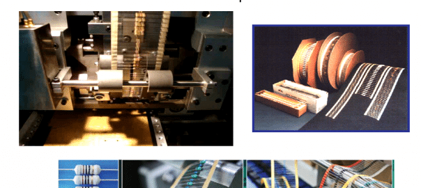
Stencil printing is a highly automated process. During machine setup, a small group of boards are misprinted. During production stencil printing, circuit boards are periodically misprinted due to clogged apertures, stencil out of alignment, solder paste rheology shifts and other issues. Stencil misprints are defined as A-Side (Initial print out of alignment with no components previously placed) and B-Side (A-Side was successfully printed and components placed and soldered. The subsequent process of printing the B-Side results in the solder paste being out of alignment resulting in a B-Side misprint).


Printed Circuit Board misprints are a costly problem with no easy rework methodology. Production cleaning processes are normally not used to clean misprint assemblies. Potential quality issues such as:

  • Solder balls collecting into the wash tank and being transferred back onto the assembly
  • Solder balls migrating into the rinse streams resulting in hazardous waste from metals in the wash and rinse holding tanks

These complexities potentially compromise repeatability and reliability standards. Due to these complex issues, most assembly houses do not allow misprints to be cleaned within their production cleaning process.


Assemblers commonly address the misprint cleaning need by either hand wiping the misprinted side of the circuit card and/or clean the misprint in a stencil cleaning machine. Both methods create the potential for quality issues. First, when wiping solder paste from the misprinted side of the board, solder paste can be trapped in solder mask defined channels, through-hole vias, and other board geometries (Figure 1). Numerous quality problems can result due to lack of control and definition.


Figure 1: Solder Balls Wedged into No Solder Mask Defined Channels and Via Holes


Second, stencil cleaning machines are designed to remove wet solder paste from stencils. Most stencil cleaning processes do not rinse the stencil with water. For those that use a water rinse, the water is reused since trace levels of metals in water prevent disposal to local treatment works. Cleaning a production board in a machine designed to clean stencils fails to meet ionic cleanliness standards required for a production assembly. Additionally, on B-Side misprints, the stencil cleaning agent is typically not adequate for cleaning reflowed flux residues on the A-Side of the board. In most cases, the stencil cleaning agent partially removes the reflowed no-clean flux residue resulting in white residue and an ionically dirty assembly.


FILTRATION OPTIONS

Cleaning the misprinted circuit board within an electronic assembly production cleaning process has the potential to achieve cleaning of wet solder paste and reflowed flux residues as well as meet quality and yield objectives. The problem with cleaning a misprinted circuit board in a production cleaning process is the deposits of solder spheres collected into the wash holding tank. Free solder spheres within the wash holding tank can be picked up by the inlet of the pump and sprayed onto production assemblies. There is also the potential that the solder spheres can be dragged into the rinse sections. Both quality and waste treatment issues result from this practice.

To resolve the quality and water treatment issues, collection and filtration method systems are needed to trap and filter solder spheres. Filtration systems designed tocontain the solder spheres and capture them prevents spraying solder balls through the pump and spray manifolds. The mechanical and filtration systems resolve the issues of redepositing solder balls onto production assemblies and the potential to contaminate rinse streams. The overriding quality advantages in using production cleaning equipment, which is designed for repeatedly removing all solder spheres from the assembly, remove reflowed flux residues and render an ionically clean printed circuit board provide a reproducible and repeatable product.

EQUIPMENT OPTIONS

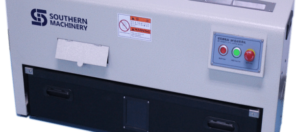
Inline Cleaning Equipment

Two types of aqueous production machines are used to clean electronic assemblies, inline and batch. For the inline machine, the pre-wash section of the cleaning machine is designed to wet, elevate the circuit board to wash temperature, and soften reflowed flux residues from production circuit assemblies. On option for containing solder balls is to equip the pre-wash sectionwith deflectors that contain the raw solder paste as it is being displaced from the circuit assembly. The deflectors close in the pre-wash spray manifolds using two trays and plates to prevent solder spheres from escaping the housing of the pre-wash section. As the boards enter the pre-wash section, the displaced solder balls and wash fluid drain into the catch trays. By capturing and containing the pre-wash liquid, the majority of the solder balls can be channeled into a series of sluice boxes. This important design feature contains the bulk of the solder balls with a minimal amount escaping to the wash holding tank.


A series of Sluice Boxes can be designed to capture the heavy raw solder spheres similar to the techniques used in mining precious metals from water streams (Figure 5). Three separate sluice boxes capture the majority of the solder paste. Each sluice box is equipped with a wire mesh. The weight of the solder balls drop through the wire mesh and collect into the sluice box trays. The first sluice box captures the majority of the solder spheres with the remaining two sluice boxes used to collect the residual solder spheres.


Figure 3: Sluice Box Collection Boxes courtesy of Speedline Technologies

Solder balls that are not collected within the sluice boxes will drain into the wash fluid holding tank. To prevent these stray solder balls from being sprayed onto circuit boards, three pump intake strainers prevent large spheres from entering the pump (Figure 6). The smaller solder spheres that pass through the strainers will be captured in a bag filter from wash liquid pumped through the outlet of the pump.


Figure 4: Strainers in Suction Inlet of the Wash Holding Tank courtesy of Speedline Technologies

Following the suction strainers, the wash solution is pumped through a filtration system designed to collect any remaining solder spheres before reaching the spray manifolds. The wash outlet enters the top side of the filtration canister, exits the clean side of the filter and then goes to the spray jets.


Figure 7: Filtration Canister

Within the canister, there are internal bars that prevent the bag filter from getting next to the exit side of the filter housing. This design feature prevents back flow or resistance as the liquid pumps through the filter canister. The 10/5 bag filter cartridge (ten microns on the inside and 5 microns on the outside of the filter cartridge) provides double redundancy to contain any solder balls from escaping the filter (Figure 9). The 10 micron side captures the heavy particles and the fine 5 micron side of the filter assures no solder spheres are sprayed onto circuit cards. The filtration design removes solder balls as small as Type 5 Solder Paste while preventing solder balls going to the manifolds. Pressure drops are minimal due to the solder paste being captured within the bag filter. Should the pressure drop, the machine is equipped with a user defined interface, which sends an alarm to the operator. The design is such that thousands of misprint boards could be cleaned before having an impact on the bath integrity, pressure and cleaning performance.

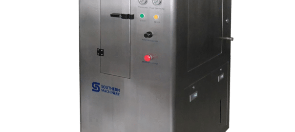
Batch Cleaning Equipment

One main difference between batch cleaning machines versus an in-line type cleaner is the ability to program the type of wash cycle, the sequence, and cycle times within the cleaning process. It is therefore critical that the ability to effectively trap and collect wet solder paste be integrated into the batch cleaner wash cycles.


The design objective is to provide the board assembler the flexibility to deflux their normal production runs (A/ B side), deflux an A-side with B-side misprint, clean A/B side misprint, plus the ability to completely rinse and dry the product within the same batch type cleaner.

Similar to the design for the in-line cleaning system, the same equipment manufacturer used the multi-stage filtration approach to effectively collect solder spheres and to prevent the spheres from being sprayed onto the board assembly. A pre-wash type cycle in the batch cleaning process will wet, elevate the circuit board to wash temperature, and soften the reflowed flux residues from the production circuit assemblies. The flux composition with the raw solder paste is easier to remove than the reflowed paste. An internal bag type filter is used to capture the raw solder paste that is removed during the Flood Wash cycle . The main purpose of the internal bag filter is to minimize the amount of solder paste that would be drained into the wash fluid holding tank.


Figure 8: Bag Filter in Wash Holding Tank

Solder spheres that are not collected in the bag filter will collect in the wash fluid holding tank. To prevent large particles from entering into the wash pumps, two intake strainers are located in the wash holding tank.


Figure 9: Batch Intake Strainers

Following the suction strainers, the wash solution is pumped through a filtration system that is designed to capture the smallest of solder spheres before being sprayed through the wash fluid spray delivery system. The filtration system is designed to capture solder paste as low as type 5 paste (Figure 10).


Figure 10: Batch Filtration Design

SUMMARY

Cleaning both A-Side and B-Side misprints has been a complex problem for assemblers. Using a stencil cleaner to clean misprints has numerous flaws. Two key issues is the inability to remove reflowed flux residues with stencil cleaning agents and poor rinsing. Notwithstanding, most assembly houses do not allow misprints to be cleaned in production cleaning machines due to the risk of contaminating product boards with stray solder balls and due to waste water metal contamination issues.


Collection and filtration systems designed into inline and batch production cleaning equipment safely captures and contains solder spheres from being sprayed onto production assemblies. Additionally, the containment and filtration systems prevent raw solder paste from entering the rinse water streams.


Using a production cleaning machine provides numerous benefits to the assembler.

  1. Recovery and rework of expensive hardware
  2. Removal of wet solder paste
  3. Containment of solder spheres
  4. Removal of reflowed flux residues
  5. Exceptional rinsing
  6. Ionically clean assemblies
  7. Repeatable
  8. Reproducible


Wiping wet solder paste from production assemblies is a bad practice. When wiping wet solder paste, solder spheres can be wedged into no solder mask defined troughs, vias and other offsets. When these solder balls become wedged, high levels of energized sprays may not be sufficient in displacing a wedged solder ball.

50% PCBA cost saving for your current AI SMT spare parts purchasing ;

After the PCB is completed, the electric elements ought to be attached in order that a functional PCB assembly is formed. There are two construction processes which can be utilized to be able to type the PCB assembly. One could be the through-hole building in which the component leads are inserted within the holes although the other one may be the surface-mount building wherein the components are situated on pads positioned around the external surfaces on the PCB. Each sorts of construction have element leads that are fixed mechanically also as electrically towards the board through a metal solder which has melted.

Additionally, you’ll find a variety of soldering solutions to become utilized as a way to connect the PCB elements to ensure that PCB assembly could be achievable.

Production that is definitely of higher volume have to be carried out by means of machine placement and bulk wave sort of soldering. Having said that, expert technicians possess the capability to solder incredibly minute parts by the hand beneath a microscope. This is typically completed together with the use of tweezers and a soldering iron with a fine tip which is made for compact volume prototypes. Yet, there are parts that are impossible to solder together with the hands just like the ball grid array.

Visit PCB auto to know more about

PCB’s which would make up the PCB assembly have conformal coating that is certainly applied by way of dipping or spraying once the elements are carried out soldering. This coat will generally protect against corrosion plus the leaking of present or achievable shorting because of condensation. PCB assembly is static sensitive, thereby; it should be placed inside antistatic bags although it can be becoming transported. Improper techniques in handling could transmit static charge by way of the board and because of this may well damage the elements.

图片2

图片1Odd-form Component Mounter