Common Failures and Maintenance of Reflow Oven

Introduction

  • The industrial ovens used to reflow solder on a printed circuit board are intricate tools. Using a combination of radiated heat and heat convection, the solder reflow oven delivers a carefully regulated flow of consistent heat to the PCB. This process completes the assembly of the board by melting the solder to form good solid solder joints between the components and the board.

Failures and Maintenance

  • When the red light is on, the buzzer long beeping non-stoppably
    Cause: Control buzzer time relay does not work; control thermocouple opens circuit; control section of the main circuit SSR is damaged.
    Solution: Check the control buzzer time relay; check the control thermocouple; check the control section of the main circuit SSR.
    2. The system automatically enters the cooling state
    Cause: PCB dropped or jammed; transport inlet and outlet electric eye damaged.
    Solution: Take out the dropped board; replace the electric eye.
    3. The start-up process heating area temperature does not rise to the set temperature
    Reason: Damaged heater; Heating point pair faulty; Solid state relay output disconnection; Exhaust too large or unbalanced left and right exhaust; Damaged photoelectric isolation device on the control board.
    Solution: replace the heater; check or replace the electric thermocouple; replace the solid-state relay; adjust the exhaust valve air plate; replace the opto-isolator.
  • Emergency switch pressed, the system is in the waiting state
    Cause: Emergency switch is pressed; line is damaged.
    Solution: Reset the emergency switch and press the start button; repair the circuit.
  • Inaccurate counting
    Cause: The sensing distance of the counting sensor is changed; the counting sensor is damaged.
    Solution: Adjust the sensing distance of the counting sensor; replace the counting sensor.

Cautions

  • Reflow oven must completely reach the set temperature (green light on) before starting to solder.
  • In the reflow soldering process, observe the temperature change in each temperature zone often, the change range is 1 ℃ (according to the reflow oven).
  • When abnormalities occur in smt reflow production, stop it immediately.
  • The size of the substrate should not be larger than the width of the conveyor belt, otherwise cardboard accidents are likely to occur.
  • Before reflow soldering, based on documents or component packaging instructions, the components can not withstand the normal welding temperature must be taken protective measures (shielding) or not be processed by reflow soldering, instead by post-welding with manual welding, or welding robot.
  • In the reflow soldering process, prevent vibration of the conveyor belt, otherwise it will cause displacement of components and disturbance of the solder joint.
  • Regularly measure the amount of air exhausted at the reflow oven vent, the amount of air exhausted directly affects the soldering temperature.

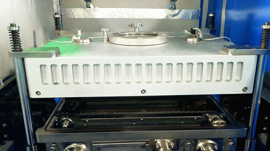
Vacuum Reflow oven S-V8000

Vacuum Reflow oven S-V8000

Applications: IGBT packaging, LED eutectic, solder paste process, high clean soldering process, laser diode package, hybrid integrated circuit package, package cover package, MEMS and vacuum package.
Industry application: S-V series vacuum reflow soldering machine is an ideal choice for R&D, process research and development, high-capacity production, and is the best choice for high-end R&D and production in military enterprises, research institutes, universities, aerospace and other fields.The product weld void rate is as low as 3% or less.

Features:

It adopts imported heating parts, uniform temperature and high thermal compensation efficiency. It is suitable for CSP, BGA, automobile lamp, UV lamp, LED flip chip process, laser device package, IGBT power device package process soldering;

Special wind wheel design, large air exchange and stable wind speed;

Each temperature zone adopts forced independent circulation, independent PID control, and independent heating mode to make the furnace cavity temperature accurate and uniform, and the heat capacity is large:
4, the temperature rises quickly, from room temperature to working temperature ≦ 30 minutes;

Imported high-quality high-temperature high-speed motor has stable wind, low vibration and low noise;

The furnace body adopts double cylinder (electric push rod) jacking device, which is safe and reliable;
7, chain, mesh belt synchronous constant speed transportation, using frequency conversion precision high speed;
8, special high-quality aluminum alloy rail design, small deformation, chain automatic refueling device;
9, UPS power-off protection function, to ensure the normal output of the PCB after power-off, not damaged;

Powerful software function, monitor and measure the temperature of the PCB board online, and analyze, store and print the data curve at any time;
11, industrial control PC and PLC communication using MODBUS protocol, work stable, to prevent the phenomenon of crash;
12, automatic monitoring, display equipment working status, you can make correction parameters at any time;

Special patented furnace design, good thermal insulation, and the lowest power consumption in the same industry;

The patented guide rail is not deformed at high temperature, and the three-wire rod synchronously widens the structure, effectively ensuring that the guide rails are parallel, preventing the board from falling, the occurrence of the card board, no cleaning, and easy adjustment. The adjustment operation can be performed both automatically and manually.

Standard chain and net chain synchronous iso-speed parallel transportation, can process single-sided and double-sided PCB boards, and optional double-rail transportation system.

The automatic width adjustment system adopts closed-loop PID control, which can be automatically adjusted to the required width according to the parameters input by the computer, and the accuracy can reach 0.2mm.

Due to the modular design of each temperature zone, hot air motor and heating wire are convenient for maintenance and repair.
18, strong cooling air cooling, cold air exchange fast, uniform wind speed, slope can be controlled by frequency conversion, tin point is smooth and bright;

The nitrogen flow meter can monitor the nitrogen flow at any time;
20, in the traditional SMT welding process, to improve, reduce the voids in the solder, the void rate can reach less than 5%;
21, high-quality products for mass production, the shortest product welding process cycle is 30S, to maintain continuous production;

At the same time, the equipment meets the traditional SMT process production configuration, nitrogen welding process and air welding process;

The vacuum part is independently controlled, and can be configured according to the process of the product, or can be shielded with the traditional process product to close this function;

ModelS-V8000
Heating part parameters
Number of pre-zones8/8
Heating zone length 3000mm
number of cooling zones2/2
Vacuum zone
Number of vacuum zones1
Product size smallest size:100*100MM;biggest size:300*350MM, 
vacuum10-100pa
Vacuum pumping speed40m³/h  Adjustable
Visual observation window1
Heating system (optional)Space maximum temperature 350 degrees
Flux recovery systemReduces equipment maintenance and increases component life
System ControlTouch Screen + Siemens PLC
Process control actionVacuuming time, vacuum pressure, vacuum pumping speed, vacuum maintenance time, deflation time free control setting
Transmission part parameters
Mesh belt width 500MM
Transport rail adjustment range 50-450MM
Transmission directionL-R(R-L)
Transportation height 900±20MM
Transmission mode mesh belt + chain transmission
Transmission speed300-2000mm/min
power supply Three five-line 380V 50/60HZ
Starting power52KW
Normal work consumption ApproxApprox.10KW
Heating time20min
Temperature control rangeRoom temperature -350 degrees
Temperature control Full computer PID closed loop control, SSR drive
Machine control modePC+PLC
Temperature control accuracy±1
PCB board temperature distribution difference±1-2
Cooling methodCold water cooling
Alarm temperature    Abnormal temperature (super high temperature or ultra low temperature after constant temperature)
Tricolor light indicationThree-color signal indicator: yellow – warming green – constant temperature red – abnormal
WeightApprox.2800kg
DimensionsL5650*W1400*H1600
Exhaust requirements 110 cubic / min   2 channels φ180mm
Nitrogen protection deviceNitrogen flow rate 20-30 cubic meters / hour oxygen concentration 500-800PPM
External water cooling systemPower 3P cooling speed ≥6 degrees / sec

DIP, PCB Assembly,Chip Mounter, Pick and Place, IC Mounter, High Speed Mounter, Wave soldering,LED lighting, LED Lamp, LED Display, LED tube,UPS, Power Converter, Power Adepter, Mobile Charger, PCB board handling system, Loader, Unloader, Conveyor,Shuttle, Chip Mounter, Pick and Place, IC Mounter, High Speed Mounter Induction Cooker, AC, Electric Cooker, Fan, TV, Settle Box

Reflow oven technology and precautions

Reflow oven technology and precautions

Far infrared reflow again

In 80s the use of far infrared reflow has the characteristics of fast heating, energy saving, stable operation, but because the printed circuit board and various components for different material, color and thermal radiation absorption rate to have very big difference, caused by a variety of different components and different parts of the circuit temperature is not uniform, the local temperature difference. For example, the black plastic package of integrated circuit will be overheated due to the high radiant absorption rate, and the welding part of it will lead to false welding on the silver lead instead of low temperature. In addition, the heat radiation blocked on printed boards, such as welding pins or small components in the shadow parts of big (high) components, will cause poor welding due to insufficient heating.

1.2 full hot air reflow again

Full hot air reflow oven  is a welding method by which the flow of airflow is forced through a convective nozzle or a heat-resistant fan, so that the welded parts are heated. This kind of equipment began to rise in 90s. Due to the adoption of this heating mode, the temperature of PCB and components is close to the temperature of the given heating area, which completely overcomes the temperature difference and shadowing effect of infrared reflow soldering, so it is widely applied now. In all hot air reflow oven  equipment, the convection velocity of the circulating gas is very important. In order to ensure that the circulating gas acts on any area of the printed board, the air flow must have a fast enough speed. To a certain extent, it is easy to cause the jitter of the printed board and the displacement of the components. In addition, in terms of heat exchange, the efficiency is poor and the power consumption is more.

1.3 infrared hot air reflow again

This kind of reflow oven is a more ideal heating method, which is based on the IR oven with hot air to make the temperature even more uniform insaide the oven. The characteristics of this kind of equipment to make full use of the infrared penetration, high thermal efficiency, energy saving, and effectively overcome the temperature difference of infrared reflow soldering and shadowing effect, and make up the influence of hot air reflow on gas flow caused by excessive demand, therefore  at international this kind of IR+Hot reflow is used most commonly  at present .

With the increase of assembly density and the appearance of fine spacing assembly technology, a reflow oven  furnace with nitrogen protection has appeared. Welding under nitrogen protection conditions can prevent oxidation, improve welding wetting power and speed up wetting speed. It is more suitable for uncleaning process to reduce the welding force and reduce welding beads.

2  The establishment of  temperature curve

The temperature curve is the curve of the temperature of a point on the SMA will change over time when SMA through the reflow oven. The temperature curve provides an intuitive method to analyze the temperature change of a component during the whole reflow process. This is very useful for obtaining the best weldability, avoiding damage to the components due to overheating, and ensuring the quality of the welding.

The following is a brief analysis of the preheating section.

2.1 preheating section

The purpose of this section is to put PCB at room temperature as soon as possible heating, to achieve second specific targets, but the heating rate should be controlled in the appropriate range, if excessive, will produce thermal shock, circuit boards and components may be damaged; if too slow, will not fully solvent, affecting the welding quality. Due to the rapid heating rate, the temperature difference in the rear section of the temperature zone is larger than that in the SMA. In order to prevent the damage of thermal shock to the component, the maximum speed is 4℃/s. However, the normal rise rate is set to 1-3℃/s. The typical heating rate is 2℃/s.

2.2 heat preservation section

The heat preservation section is the area where the temperature rises from 120℃-150℃ to the melting point of the solder paste. Its main purpose is to make the temperature of each element in the SMA stable and minimize the temperature difference.In this area, the temperature of the larger components can have enough time to catch up with the smaller components and ensure that the flux in the solder paste is fully volatile. The oxide of the soldering plate, the solder ball and the pin of the element is removed, and the temperature of the entire circuit board is balanced until the end of heat preservation section. It should be noted that all elements on the SMA should have the same temperature at the end of heat preservation section, otherwise, entering the reflux section will cause various bad welding phenomena due to the uneven temperature of each part.

2.3 reflow  section

In this area, the temperature of the heater is set to the highest, which makes the temperature of the component up to the peak temperature. In reflow sectionthe,the different of peak temperature is according to the solder paste to change, the general recommendation for solder melting point temperature plus 20-40℃. For 63Sn/37Pb solder paste with melting point of 183℃ and Sn62/Pb36/Ag2 solder paste with melting point of 179℃, the peak temperature is generally 210-230℃. Reflow time should not be too long to prevent adverse effects on SMA. The ideal temperature curve is the smallest area covered by the “tip zone” of the solder melting point.

DIP, PCB Assembly,Chip Mounter, Pick and Place, IC Mounter, High Speed Mounter, Wave soldering,LED lighting, LED Lamp, LED Display, LED tube,UPS, Power Converter, Power Adepter, Mobile Charger, PCB board handling system, Loader, Unloader, Conveyor,Shuttle, Chip Mounter, Pick and Place, IC Mounter, High Speed Mounter Induction Cooker, AC, Electric Cooker, Fan, TV, Settle Box

Reflow oven process principle and introduction

The reflow oven process principle and introduction

As we know,reflow oven is the most important welding technology in surface mount technology. It has been widely used in many industries including mobile phones, computers, automotive electronics, control circuits, communications, LED lighting and many other industries. More and more electronic devices are converted from through hole to surface mount, and reflow oven  replaces wave  soldering is a obvious  trend in welding industry.

So what is the role of reflow oven equipment in the increasingly mature lead-free SMT process? Let’s take a look at the whole SMT surface mount line:

The whole SMT surface mounting line consists of three parts, such as steel mesh solder paste printing machine, SMT machine and reflow oven furnace. For the machine, and compared with lead free, and no new demands on the equipment itself; for screen printing machine, and a lead-free solder paste in the physical properties there are some differences, so put forward some improvement on the device itself, but there is no qualitative change. the key of lead-free  is  in the reflow oven.

The lead paste (Sn63Pb37) melting point of 183 degrees, if you want to form a good weld must have the thickness of 0.5-3.5um intermetallic compounds in welding, intermetallic compound formation temperature is above the melting point of 10-15, the lead welding is 195-200. The maximum withstand temperature of the electronic device on the circuit board is generally 240 degrees. Therefore, for lead welding, the ideal welding process window is 195-240 degrees.

Because of the change of melting point of lead-free solder paste, lead-free welding has brought great changes for welding process. At present, the lead-free solder paste is Sn96Ag0.5Cu3.5 and the melting point is 217-221 degrees. Good lead-free solder must also be formed 0.5-3.5um thickness intermetallic compounds, intermetallic compound formation temperature is also above the melting point of 10-15 degrees, for lead-free welding, that is, 230-235 degrees. Since the highest temperature of lead-free solder electronic device will not change, therefore, for lead-free soldering, ideal welding process window is 230-245 degrees.
The substantial reduction of process window brings great challenge to ensure welding quality, and also brings higher requirements to stability and reliability of lead-free wave soldering equipment. Because the equipment itself is coupled with the electronic device transverse temperature difference, due to differences in size of heat capacity will produce temperature difference in the heating process, so in the process control of lead-free reflow oven can be adjusted in the process of welding temperature window becomes very small, this is the real lead-free reflow to the difficulty.